
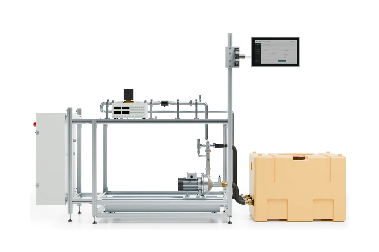
 Test engineering
Surge testing of motor windings: finding interturn faults before the motor fails
The surge test finds turn-to-turn, coil-to-coil and phase-to-phase shorts that resistance and insulation measurements often miss. A steep voltage pulse excites the winding to a damped oscillation; an interturn fault reduces the inductance and increases the frequency. For a 400 V motor, EASA AR100 recommends a test voltage of 1.8 kV peak.

How does surge testing work?
The tester charges a capacitor and discharges it abruptly through the winding. Capacitor and winding form a resonant circuit, and a damped oscillation results. An interturn fault reduces the inductance of the winding, the oscillation becomes faster and deviates from the reference curve.
The frequency of the resonant circuit shows why this is so:
f = 12π · √(L · C)
- f
- frequency of the decaying oscillation in Hz
- L
- inductance of the winding under test in H
- C
- capacitance of the test circuit in F, essentially the surge capacitor of the tester
Example: With 20 mH and 0.5 µF the circuit oscillates at around 1.59 kHz. If the inductance drops by 10 % to 18 mH due to an interturn fault, the frequency rises to around 1.68 kHz, a good 5 %. The zero crossings of the curve shift to the left.
A short-circuited ring of one or more turns acts like the short-circuited secondary winding of a transformer. The current flowing in it weakens the flux in the coil. This is why the effective inductance drops significantly, although the DC resistance hardly changes. In addition, the damping increases and the curve decays faster.
There are three ways of comparing:
- Phase to phase (line to line, L-L): On a three-phase motor, all three curves should be almost identical.
- Against a reference: an identical, intact winding or a stored curve.
- Pulse to pulse (P-P): The voltage rises in small steps, and each curve is compared with the previous one. If it changes abruptly from a certain voltage, the turn insulation has given way at that point.
The pulse stresses above all the insulation between the turns. With a steep edge, a large part of the voltage is applied across the first turns of the coil. This is why the rise time is just as important for the test as the peak value.
Which faults does the surge test find and which not?
The surge test finds faults in the turn insulation: turn-to-turn, coil-to-coil, layer-to-layer and phase-to-phase shorts, as well as incorrect numbers of turns and connection errors. It does not find earth faults, contact resistances or broken parallel conductors, because the result hardly depends on the ohmic resistance.
| Fault | Surge test | Suitable test |
|---|---|---|
| Turn-to-turn, coil-to-coil, layer-to-layer short | yes | Surge test |
| Phase-to-phase short, incorrect number of turns, connection error | yes | Surge test, resistance per phase |
| Earth fault, weak main insulation | no | Insulation resistance, high-voltage test |
| Contact resistance, broken parallel conductor, wrong wire cross-section | no | Winding resistance |
| Partial discharge in converter operation | indications only | Partial discharge measurement (RPDIV) |
This is why the surge test does not replace any other measurement; it closes a gap. How resistance, insulation and polarisation index are measured is described in our article Measuring motor windings.
Which test voltage applies to a 400 V motor?
For a 400 V motor with a random-wound winding, 1.8 kV peak is common. This results from the formula in the repair standard ANSI/EASA AR100, which is the most widely used for low-voltage motors. There is no IEC standard with a fixed test level for random-wound windings.
US = 2 · UN + 1,000 V
- US
- surge test voltage, peak value in V
- UN
- rated voltage of the motor, RMS value line to line in V
Example: 400 V motor: 2 · 400 V + 1,000 V = 1,800 V. For 690 V the result is 2,380 V.
For form-wound windings of high-voltage machines, IEEE 522 gives the value in “per unit”. One per unit is the peak value of the line-to-earth voltage:
US = 3.5 · √2√3 · UN ≈ 2.86 · UN
- US
- surge test voltage for new, cured form-wound coils, peak value in kV
- UN
- rated voltage line to line in kV
- 3.5
- test level in per unit according to IEEE 522
Example: 6.6 kV motor: 2.86 · 6.6 kV = 18.9 kV. Used windings are tested at 75 % of this, 14.1 kV.
| Winding | Test voltage (peak value) | Basis |
|---|---|---|
| 400 V, random-wound | 1.8 kV | EASA AR100 |
| 690 V, random-wound | 2.38 kV | EASA AR100 |
| 6.6 kV, form-wound coils in service | 14.1 kV | IEEE 522, 75 % of 3.5 per unit |
| 6.6 kV, form-wound coils new and cured | 18.9 kV | IEEE 522, 3.5 per unit |
| 6.6 kV, single coil before installation | 20.4 kV | IEC 60034-15, 0.65 of (4 UN + 5 kV) |
According to IEEE 522, the rise time of the pulse is 0.1 to 0.2 µs; IEC 60034-15 specifies 0.2 µs with a tolerance of 0.1 µs. For motors already in service, we test with reduced voltage and agree the value with you in advance.
A common confusion: the same formula, twice the rated voltage plus 1,000 V, also applies to the high-voltage test to earth. There it is an RMS value over one minute; in the surge test it is the peak value of a pulse. The two tests stress the insulation at different points.
How is the error area ratio (EAR) calculated and evaluated?
The error area ratio (EAR) is the area between two curves divided by the area under the reference curve, in percent. The method goes back to a patent by Baker Instrument and is used in most testers today. No standard specifies EAR limit values.
EAR = Σ |uref,i − utest,i|Σ |uref,i| · 100 %
- EAR
- error area ratio in %
- uref,i
- voltage of the reference curve at sampling point i in V
- utest,i
- voltage of the tested curve at the same sampling point in V
- Σ
- sum over all sampling points of the curve
Example: The absolute deviations add up to 1,140 V over all sampling points, the absolute values of the reference curve to 15,200 V. EAR = 1,140 / 15,200 · 100 % = 7.5 %.
Manufacturers give their own guide values. The following table shows the recommendation of the tester manufacturer Electrom as an example:
| Comparison | Pass | Check more closely | Fail |
|---|---|---|---|
| Phase to phase, removed stator | below 8 % | 8 to 30 %: check pulse to pulse | above 30 % |
| Phase to phase, assembled motor | below 8 % | above 8 %: check pulse to pulse | not specified |
| Pulse to pulse, all windings | below 10 % | 10 to 30 %: check the progression over the voltage | above 30 % |
Such values are a starting point, not a fixed rule. Concentric windings can show up to about 20 % even without a fault because of coils of different lengths. In the pulse-to-pulse comparison, the pattern counts: individual high deflections above 30 % indicate a flashover, many medium deflections at high voltage indicate partial discharges. In the end, what is meaningful is the comparison with identical motors and with earlier measurements on the same motor.

How does a surge test run step by step?
Winding resistance and insulation resistance come first, and only then high voltage and the surge test. If the insulation value is too low, the winding is first dried or repaired, because the surge voltage would put additional stress on the weak insulation. The actual measurement per phase is done quickly; the preparation determines the quality.
- Preliminary test: winding resistance per phase with temperature, insulation resistance and, if required, polarisation index.
- Prepare the test item: isolate it, disconnect the supply cable and converter, disconnect PTC thermistors, heaters and sensors. With delta connection, remove the links if possible.
- Secure the test area: earth the enclosure, cordon off the test area. Testing is carried out at a test station to DIN EN 50191, only by instructed qualified electricians.
- Ramp up the voltage: start with a low voltage and increase in steps up to the test voltage. The pulse-to-pulse comparison runs alongside.
- Compare the phases: test the three phases one after the other, overlay the curves, read the EAR.
- Clarify anomalies: on an assembled motor, turn the rotor and repeat, look at the pattern of the pulse comparisons, compare with the reference curve.
- Finish: discharge the winding, save the curves with serial number, voltage and temperature in the test report.
For a rewind, AR100 recommends also testing the inserted winding before it is connected. A fault found before impregnation is much cheaper to rectify.
Hazards and limits
The surge capacitor stores energy that can remain at the terminals even after switching off. Only touch test probes and terminals after discharge, and leave the winding earthed until you reconnect. A flashover during the test can further damage the insulation at the fault location; that is the price for the fault occurring on the test bench and not in operation.
The method has limits with small motors with a heavily damped curve, with single-phase motors without a phase for comparison and with welded shorts on an assembled motor. In these cases the pulse-to-pulse comparison, a reference curve from an identical motor and a test run with comparison of the phase currents help.
Which misinterpretations occur in surge testing?
Most misinterpretations come from the installed rotor, from the connection and from curves without comparison. If you know these cases, you reject fewer good motors and overlook fewer bad ones.
- Installed rotor: The rotor damps the oscillation, and depending on the rotor position the phases differ. The pulse-to-pulse comparison is independent of this, because each phase is compared with itself. For the phase comparison, turn the rotor until the curves coincide.
- Welded interturn fault: A permanently welded short does not change with increasing voltage and does not show up in the pulse-to-pulse comparison. The phase comparison helps here.
- Delta connection: The phases not under test form a parallel path and change the curve. If possible, remove the links.
- Testing via the supply cable: The capacitance of a long cable changes frequency and damping. Test at the terminal board of the motor.
- Synchronous machines: Disconnect the excitation and lift the brushes, otherwise diodes of the excitation can be damaged.
- Curves without reference: A single curve says little. Save the curves of every motor so that there is a comparison next time.
Is the surge test sufficient for motors on a frequency converter?
For motors on a frequency converter, the surge test is a good start, but it does not replace partial discharge testing. Converters generate steep voltage edges that put permanent stress on the turn insulation. IEC 60034-18-41 describes how insulation systems are evaluated for this operation via the repetitive partial discharge inception voltage (RPDIV).
In the pulse-to-pulse comparison, partial discharges often show up as many medium deflections shortly before the test voltage. This is an indication, but not a measurement of the inception point. For motors that run on a converter again after a rewind, the surge test is particularly worthwhile, because it finds weakened turn insulation before the converter breaks it down.
What should you look for when buying a winding tester or motor test bench?
What matters are test voltage and rise time for your largest motors, automatic evaluation with error area and stored reference curves, and a test report for each motor. If you test many motors, you also need a fixed sequence in which resistance, insulation, high voltage and surge test run one after the other.
The effort for a test solution is determined mainly by the voltage class and size of the motors, the number of motor types with their own connection and mounting, whether high-voltage and surge testing run together in one test chamber and how the test data get into your systems.
| Criterion | What to look for |
|---|---|
| Test voltage | sufficient for the highest value to AR100 or IEEE 522 for your motors |
| Rise time | 0.1 to 0.2 µs, as specified in IEEE 522 and IEC 60034-15 |
| Energy | enough for large windings with low inductance, otherwise the voltage at the test item collapses |
| Evaluation | EAR for phase to phase and pulse to pulse, limit values for each motor type, reference curves |
| Scope of testing | surge test alone or with resistance, insulation, PI and high voltage in one sequence |
| Safety | test station to DIN EN 50191 with access protection and emergency stop |
| Data | test report with serial number, test history, data interface to the ERP system |
If you only test occasionally, winding testing as a service is often more economical than your own tester. As a service, we test windings in Wörth an der Donau; get in touch with us. For your own testing, we integrate the surge test as an option into the NIKLAS Motor Bench, with the curves in the test report for each motor. The NIKLAS Test Software guides you through the sequence, evaluates the measured values against the limit values for each test item and transfers the data to your ERP system.
Frequently asked questions about surge testing
Answers on test voltage, risks, evaluation and the choice between your own tester and a service provider.
Can surge testing damage the motor?
Intact insulation withstands the test. If the turn insulation is already weakened, it can break down during the test. That is intended: the fault shows up on the test bench and not in operation. For motors already in service we therefore test with reduced voltage.
Does the rotor have to be removed for the surge test?
No. However, the installed rotor influences the curves in the phase comparison. On an assembled motor we use the pulse-to-pulse comparison, which is independent of the rotor position, and for the phase comparison we turn the rotor to a suitable position.
Which test voltage applies to a 400 V motor?
According to EASA AR100, twice the rated voltage plus 1,000 V, so 1.8 kV peak. The rise time is usually 0.1 to 0.2 µs. For used windings we agree a reduced value.
Does the surge test also find earth faults?
No. Earth faults and weak main insulation are shown by insulation resistance and the high-voltage test to earth. The surge test checks the insulation between the turns.
What does an error area of 12 % mean?
In the phase comparison, depending on the manufacturer, this is in the range in which a closer check is advisable. Compare with identical motors and test pulse to pulse. With concentric windings such a value can also occur without a fault.
Do motors on a frequency converter need a separate test?
Converters generate steep voltage edges that put additional stress on the turn insulation. For motors on a converter, IEC 60034-18-41 describes the evaluation via the partial discharge inception voltage. The surge test gives indications of partial discharges but does not replace this measurement.
Buy your own surge tester or have testing done as a service?
Your own tester pays off if you regularly repair or rewind motors and want to compare the curves over years. For individual motors, testing as a service is usually cheaper. We test windings as a service in Wörth an der Donau.
Can the surge test be integrated into a motor test bench?
Yes. On the NIKLAS Motor Bench we integrate the surge test as an option into the test bench software and the test report. It then runs in the same guided sequence as resistance, insulation and high voltage, and the curves remain stored for each motor.
What information do you need for a quotation?
Motor types with rated voltage, power and frame size (a photo of the rating plate is sufficient), plus quantities and the tests you carry out. Tell us whether you want to test yourself or have testing done. We will get back to you personally within 4 working hours.
More technical articles
Test engineering Test engineering
Test bench requirements specification
Test items, power, measurement uncertainty, cycle time, energy and acceptance with formulas and worked examples: what a requirements specification for a test bench must contain. Test engineering
AI vision inspection
Resolution, lens, exposure, sample parts, escapes and false rejects with formulas and worked examples: how to design an AI vision inspection and accept it.Enquire about surge testing for your motors
State motor types, rated voltage and quantity. We will tell you whether testing as a service or a Motor Bench with surge test is the better fit.
Simon Niklas
Mechanical engineer, M.Sc.
+49 941 56956720[email protected]
“Good engineering proves itself in day-to-day production. That is why we combine technical planning with a close understanding of process, operation and maintenance.”
Book a consultation