
 Test engineering
Measuring motor windings: resistance, insulation and polarisation index
You test a motor winding with three measurements: winding resistance per phase, insulation resistance to earth with polarisation index, and a test for inter-turn faults. The phase resistances should differ only slightly from one another, and according to IEEE 43 the insulation resistance of a random-wound winding should be at least 5 MΩ at 40 °C. The values only become meaningful with temperature correction and comparison with earlier measurements.

Which measurements show the condition of a motor winding?
Four measurements show the condition of a motor winding: winding resistance per phase, insulation resistance to earth, polarisation index and a test for inter-turn faults. Each measurement finds a different type of fault. Only together and in comparison with previous values do they tell you whether the motor can continue running.
| Measurement | What it finds | Instrument | Evaluation |
|---|---|---|---|
| Winding resistance | Open circuit, loose connection, wrong connection, severe inter-turn faults | Low-resistance ohmmeter using the four-wire method | Phases against each other, manufacturer value at 20 °C |
| Insulation resistance, IR | Moisture, dirt, earth fault, aged main insulation | Insulation tester with DC voltage | Minimum value to IEEE 43 at 40 °C, trend |
| Polarisation index (PI), DAR | damp or contaminated insulation | Insulation tester with timer function | Minimum PI by thermal class |
| Inter-turn fault | Short circuit between turns of the same coil | Inductance or impedance measurement, surge test | Phase comparison, waveform comparison |
All static measurements leave one gap: they do not show bearing damage, unbalance or problems in the rotor. For that, you need a test run with current, vibration, temperature and run-down time.
How do you measure winding resistance correctly?
You measure the DC resistance of each phase winding with a low-resistance ohmmeter using the four-wire method and note the winding temperature. Then you convert to 20 °C and compare the phases with each other and with the manufacturer value. A normal multimeter is not sufficient for values below about 1 Ω, because the test leads and contacts themselves are already in the range of tenths of an ohm.
Procedure at the terminal board
- Isolate the motor, secure it against reconnection, verify that it is de-energised. Disconnect the supply cable and frequency inverter.
- Photograph the position of the links, then remove the links. This way you measure each phase winding individually: U1 to U2, V1 to V2, W1 to W2.
- Place the current clamps and voltage taps directly on the terminal studs, with the voltage taps on the inside.
- Wait until the value is stable. The inductance of the winding delays the measuring current (see formula below).
- For very small values, measure twice with reversed current and take the average. This cancels out thermoelectric voltages at the contacts.
- Measure the winding temperature. If the motor has been at a standstill for several hours, it corresponds to the room temperature.
If the links cannot be removed, measure between the outer terminals U, V and W. You then have to take the connection into account:
Rphase = Rterminal2 (star) or Rphase = 1.5 · Rterminal (delta)
- Rphase
- resistance of one phase winding in Ω
- Rterminal
- measured resistance between two outer terminals in Ω
Example: A motor in delta connection shows 1.80 Ω between U and V. The phase resistance is 1.5 · 1.80 Ω = 2.70 Ω. In star connection it would be 0.90 Ω.
Copper changes its resistance by around 0.4 % per kelvin. A value from a warm motor is therefore not comparable with a value from a cold one. Motor manufacturers usually state the winding resistance for 20 °C. The conversion for copper with the constant 235 from DIN EN 60034-1 is:
Rθ2 = Rθ1 · 235 + θ2235 + θ1
- Rθ1
- measured resistance in Ω
- θ1
- winding temperature during measurement in °C
- θ2
- reference temperature in °C, usually 20 °C
- Rθ2
- resistance at reference temperature in Ω
- 235
- material constant for copper in K (aluminium: 225; US standards use 234.5 for copper)
Example: You measure 1.250 Ω at 32 °C. At 20 °C, this is 1.250 Ω · 255 / 267 = 1.194 Ω. Without conversion, the value would be around 5 % too high.
The time constant of the winding shows how long you have to wait until the measured value is stable:
τ = LR
- τ
- time constant in s
- L
- inductance of the phase winding in H
- R
- resistance of the measuring circuit in Ω
Example: With 0.2 H and 0.5 Ω, τ = 0.4 s. After about five time constants, i.e. 2 s, the value deviates by less than 1 % from the final value. Large machines with very low resistance need seconds to minutes.
Typical measurement errors are crocodile clips on oxidised studs, measuring via the supply cable instead of at the terminal board, a motor that is still warm with no temperature noted, and reading the value before it is stable.
How large may the unbalance between the phases be?
The unbalance is the largest deviation of one phase winding from the mean of the three phase windings, in per cent. There is no generally applicable standard limit for it. In an intact winding, the phases are close together; if they differ by more than a few per cent, the motor should not be switched on until the cause has been clarified.
ΔR = max |Ri − Rm|Rm · 100 %
- ΔR
- resistance unbalance in %
- Ri
- resistance of phase windings U, V and W in Ω
- Rm
- mean of the three phase resistances in Ω
Example: The measured values are 1.212 Ω, 1.205 Ω and 1.231 Ω. The mean is 1.216 Ω; W has the largest deviation at 0.015 Ω. ΔR = 0.015 / 1.216 · 100 % = 1.2 %.
These decision rules help in practice:
- One phase stands out clearly: first check the terminals, links and connecting leads in the motor. A higher value indicates a loose connection or a broken parallel conductor, a lower value indicates short-circuited turns.
- All phases equal, but different from the manufacturer value: check the temperature correction and connection, then consider incorrect winding data after a rewind.
- Resistance unremarkable, motor still runs hot: an inter-turn fault involving a few turns hardly changes the DC resistance. Then inductance comparison and surge test follow.
It is best to define the limit value in the test specification, agreed with the motor manufacturer and separately for rewound and existing motors. For inductance and impedance comparison, you measure the phase windings with AC voltage. An inter-turn fault lowers the inductance of the affected phase much more than its resistance. With the rotor installed, the rotor position changes the values; turn the rotor and compare at the same position.
Which test voltage and which minimum value apply to insulation testing?
For motors up to 1,000 V rated voltage, you measure the insulation resistance to IEEE 43 with 500 V DC and read the value after one minute. At 40 °C, it should be at least 5 MΩ for random-wound windings and at least 100 MΩ for newer form-wound windings. Higher rated voltages need higher test voltages.
| Rated voltage of the winding | Test voltage (DC) |
|---|---|
| below 1,000 V | 500 V |
| 1,000 to 2,500 V | 500 to 1,000 V |
| 2,501 to 5,000 V | 1,000 to 2,500 V |
| 5,001 to 12,000 V | 2,500 to 5,000 V |
| above 12,000 V | 5,000 to 10,000 V |
| Winding type to IEEE 43 | Minimum value R1min at 40 °C |
|---|---|
| Random-wound windings and form-wound coils below 1 kV | 5 MΩ |
| AC windings with form-wound coils, built after about 1970 | 100 MΩ |
| Windings before about 1970, field windings, others | rated voltage in kV + 1 MΩ |
Some motor manufacturers state their own values, which take precedence. VEM, for example, states in its manual for explosion-protected motors 2.5 to 6.3 kΩ per volt of rated voltage at 25 °C depending on power, so around 2.5 MΩ for a 400 V motor up to 10 kW.
Insulation resistance falls sharply as temperature rises. IEEE 43 therefore refers the values to 40 °C. As an approximation, the value halves for every 10 K rise in temperature:
R40 = RT · 0.5(40 − T) / 10
- R40
- insulation resistance referred to 40 °C in MΩ
- RT
- measured insulation resistance in MΩ
- T
- winding temperature during measurement in °C
Example: You measure 800 MΩ at 20 °C. Referred to 40 °C, this is 800 MΩ · 0.52 = 200 MΩ. For the trend, it is best to compare values at a similar temperature.
How to measure insulation resistance
- Disconnect the inverter, soft starter and electronics. Do not apply the test voltage to temperature sensors such as PTC thermistors; PTC thermistor manufacturers such as SEVA permit at most 2.5 V DC for measurement.
- With the links removed, measure each phase winding to earth while connecting the other phase windings to earth. This way you test the earth and phase-to-phase insulation in one step.
- Select the test voltage according to the table, read the value after 1 minute, and continue measuring up to 10 minutes for PI.
- Note the winding temperature and humidity.
- After the measurement, discharge the winding via a resistor. Megger recommends a discharge time of at least four times the measuring time; after a 10-minute PI test, leave it earthed for 40 minutes.
How do you calculate the polarisation index and DAR?
The polarisation index is the insulation resistance after 10 minutes divided by the value after 1 minute. Dry, clean insulation polarises slowly and the value rises considerably; with damp or contaminated insulation, it stays almost the same. IEEE 43 requires a PI of at least 2.0 for thermal class B and above.
PI = Riso,10minRiso,1min
- PI
- polarisation index (dimensionless)
- Riso,10min
- insulation resistance after 10 minutes in MΩ
- Riso,1min
- insulation resistance after 1 minute in MΩ
Example: 1,200 MΩ after 10 minutes and 400 MΩ after 1 minute give PI = 3.0.
The dielectric absorption ratio (DAR) is the short version for the workshop. It needs only 60 seconds:
DAR = Riso,60sRiso,30s
- DAR
- dielectric absorption ratio (dimensionless)
- Riso,60s
- insulation resistance after 60 seconds in MΩ
- Riso,30s
- insulation resistance after 30 seconds in MΩ
Example: 480 MΩ after 60 seconds and 320 MΩ after 30 seconds give DAR = 1.5.
| Condition of the insulation | DAR (60 s / 30 s) | PI (10 min / 1 min) |
|---|---|---|
| dangerous | below 1.0 | below 1.0 |
| questionable | 1.0 to 1.25 | 1.0 to 2.0 |
| good | 1.4 to 1.6 | 2.0 to 4.0 |
| very good | above 1.6 | above 4.0 |
The table is a widespread rule of thumb from Megger documentation, not a standard. The binding values under IEEE 43 are the minimum values: PI 1.5 for thermal class A and 2.0 for classes B, F and H. If the one-minute value is above 5,000 MΩ, the PI is no longer meaningful according to IEEE 43, because the currents are in the range of the measuring accuracy. Even in small motors with random-wound windings, the absorption current often decays so quickly that the PI says little. Then the insulation value itself and its trend are what count.
Which tests belong in the incoming and final inspection of a motor repair?
The incoming inspection clarifies what is wrong with the motor and whether the repair is worthwhile. The final inspection proves that the motor is in order again and provides the reference values for all later measurements. Both follow the same sequence: from the gentle to the stressing test.
| Test | Incoming inspection | Final inspection |
|---|---|---|
| Visual inspection, rating plate, terminal board | yes | yes |
| Winding resistance per phase, converted to 20 °C | yes | yes |
| Insulation resistance, PI or DAR | yes | yes |
| High-voltage test to earth | only with a good insulation value | yes |
| Surge test | if an inter-turn fault is suspected | yes, especially after a rewind |
| Test run: direction of rotation, no-load current per phase, vibration, bearing temperature | if the motor may run | yes |
The high-voltage test to earth runs for one minute with AC voltage according to DIN EN 60034-1:
UP = 2 · UN + 1,000 V
- UP
- test voltage, RMS value in V
- UN
- rated voltage of the motor in V
Example: For a 400 V motor, this gives 2 · 400 V + 1,000 V = 1,800 V. A repeat test is only permitted at 80 %, i.e. 1,440 V.
Repairers test used windings with a considerably reduced voltage; VEM states at least 1,000 V for windings in service. Carry out this test at a protected test station to DIN EN 50191. For the test run, VEM states a tolerance of ±15 % from the manufacturer value for the no-load current; the currents of the three phases should differ from each other by at most 15 %. You evaluate vibration to ISO 20816 or DIN EN 60034-14. How to find inter-turn faults with certainty is explained in the article Surge testing of motor windings.
How do you narrow a fault down to the motor or the supply cable?
Disconnect the motor at the terminal board from the supply cable and inverter, and measure both parts separately. If the motor alone is unremarkable, the fault lies in the cable, terminal point or inverter. The following table assigns typical findings to a cause and the next step.
| Finding | Probable cause | Next step |
|---|---|---|
| Low insulation value, PI below 2 | Moisture, dirt | clean, dry, measure again |
| Insulation value close to 0, PI not measurable | Earth fault | measure phase windings individually, locate the fault |
| One phase with higher resistance | loose connection, broken parallel conductor | check terminals and soldered joints |
| One phase with lower resistance or lower inductance | Inter-turn fault | Surge test |
| Resistance and insulation good, current unbalance in operation | Supply voltage unbalance, rotor fault, inter-turn fault under voltage | measure supply voltage, surge test, test run |
| Electrically all good, motor noisy or hot | Bearings, unbalance, alignment | vibration, temperature, run-down time |
Measure the supply cable with the same test voltage as the motor. With long cables to the inverter, a weak insulation value is often found on the cable, not on the motor.
Your own motor test bench or testing by a service provider?
Your own motor test bench pays off if you test motors regularly, need results quickly and want to build up a test history for each motor. With only a few motors a year or rare special tests, a testing service provider is usually the better choice. A mix often makes sense: routine testing in-house, special cases outside.
| Criterion | Own test bench | Testing service provider |
|---|---|---|
| Test volume | many motors, recurring | individual motors, irregular |
| Lead time | no transport, immediately in-house | transport and scheduling |
| Test history | every measurement against the same limit values, trend per motor | depends on the service provider’s report |
| Staff | your own staff after instruction | no in-house testing expertise needed |
| Costs | investment, then low costs per test | no investment, costs per job |
What determines the effort for a test bench: power and size range of the motors, testing at no load or under load, direct torque measurement with a torque flange, number of motor types with their own fixture, high-voltage and surge testing in the test chamber, and the connection to your ERP system.
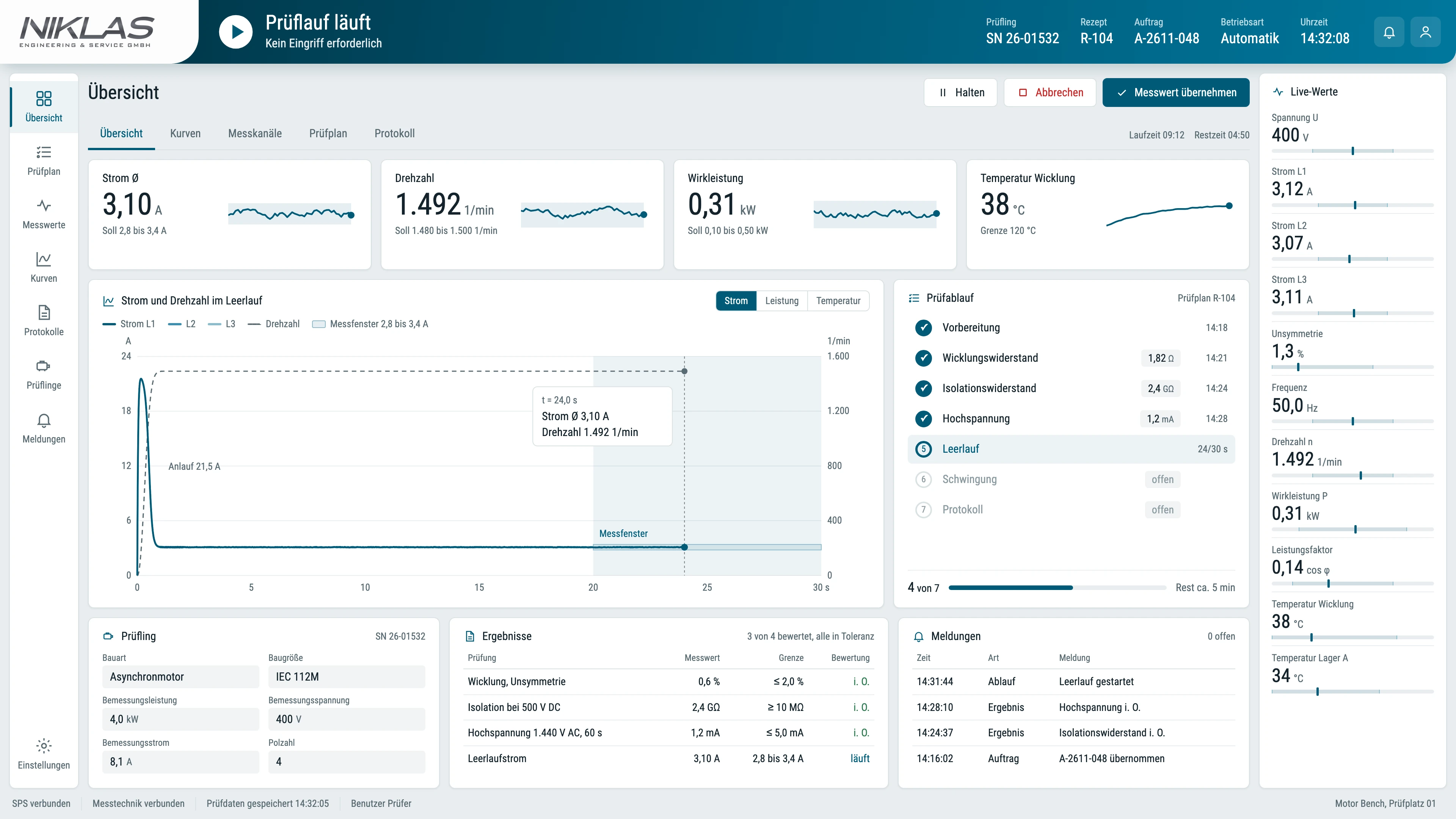
The NIKLAS Motor Bench measures insulation resistance, winding resistance, high-voltage strength, current, voltage, power with current unbalance, speed, temperature, vibration and run-down time in a guided sequence. We define test profiles and limit values with the motor manufacturer, and we integrate the surge test as an option. The NIKLAS Test Software stores measured values and test history for each motor and transfers the data to your ERP system. For a quotation, we need the motor types with voltage, power, frame size and shaft diameter (a photo of the rating plate is enough), the tests you require, quantities and your installation site.
Frequently asked questions about measuring motor windings
Answers on measuring methods, limit values, troubleshooting and the choice between your own test bench and a service provider.
How do I measure the winding resistance of an electric motor?
Remove the links at the terminal board and measure each phase winding with a low-resistance ohmmeter using the four-wire method. Note the winding temperature, convert to 20 °C and compare the three phases with each other and with the manufacturer value.
What insulation resistance is acceptable for a 400 V motor?
According to IEEE 43, you measure with 500 V DC; a random-wound winding should reach at least 5 MΩ after one minute, referred to 40 °C. Intact, dry windings are usually far above this. More important than the single value is whether the value is falling compared with earlier measurements.
What is a good PI value?
IEEE 43 requires a polarisation index of at least 2.0 for thermal classes B, F and H, and 1.5 for class A. Values between 2 and 4 are considered good. Above 5,000 MΩ insulation resistance, the PI is no longer meaningful.
How do I detect an inter-turn fault in a motor?
An inter-turn fault often hardly shows in the DC resistance. It is more likely to show when you compare the inductance and impedance of the phases. The surge test, which compares the oscillation response of the phases, is the surest way to find it.
May I measure a motor on a frequency inverter with an insulation tester?
Only if you disconnect the inverter first. The test voltage of 500 V or more can damage the electronics, and the inverter distorts the measured value. PTC thermistors and other temperature sensors do not belong in the measuring circuit either.
Is it worth having your own motor test bench for maintenance?
Your own test bench pays off if you test motors regularly and want to build up a test history for each motor. You save transport and waiting time, and every test measures against the same limit values. With only a few motors a year, a service provider is usually cheaper.
Who operates the Motor Bench, and how long does a test take?
After instruction, your staff carry out the test themselves; the software guides them step by step through the sequence, fully or semi-automatically. A test takes about 15 minutes, depending on the motor type and test program.
Can the test data be transferred to our ERP system?
Yes. The NIKLAS Test Software stores measured values, serial number and test date for each motor and transfers the data to your ERP system via a data interface. We define with you during configuration which data are transferred in which format.
What information do you need for a quotation for a motor test bench?
Motor types with voltage, power, frame size and shaft diameter; a photo of the rating plate is enough. Plus the tests you require, whether with load and torque flange, quantities, installation site, mains connection and the required data interface. We get back to you personally within 4 working hours.
More technical articles
Test engineering Test engineering
Pump testing ISO 9906
Tolerances of grades 1B, 2B and 3B, head and efficiency with a worked example, measurement uncertainty, NPSH3 and test procedure: how a pump test to DIN EN ISO 9906 runs on the test bench. Test engineering
Test bench requirements specification
Test items, power, measurement uncertainty, cycle time, energy and acceptance with formulas and worked examples: what a requirements specification for a test bench must contain.Enquire about a Motor Bench for your maintenance
Tell us the motor types, power range and the tests you carry out. We get back to you personally within 4 working hours with a proposal for the test program and equipment.
Simon Niklas
Mechanical engineer, M.Sc.
+49 941 56956720[email protected]
“Good engineering proves itself in day-to-day production. That is why we combine technical planning with a close understanding of process, operation and maintenance.”
Book a consultation