
 Test engineering
Pump testing to DIN EN ISO 9906: acceptance grades, formulas and test procedure
DIN EN ISO 9906 governs the hydraulic acceptance test of rotodynamic pumps. The agreed acceptance grade defines how far flow rate, head and efficiency may deviate from the guarantee point, for grade 1B for example ±5 % for the flow rate and ±3 % for the head. These tolerances already include the measurement uncertainty of the test bench.

What does DIN EN ISO 9906 govern in pump testing?
DIN EN ISO 9906 specifies how the hydraulic performance of rotodynamic pumps is measured and evaluated for acceptance by the customer. It applies to centrifugal, mixed flow and axial pumps of any size on test benches of manufacturers or laboratories, with liquids that behave like clean, cold water. The current edition is DIN EN ISO 9906:2013-03, the German version of ISO 9906:2012.
The core of the standard is the guarantee point: an operating point of flow rate and head that the manufacturer guarantees. The acceptance test shows whether the measured characteristic curve reaches this point within the tolerance of the agreed grade.
The standard describes several forms of acceptance: the factory test without the customer, the factory test signed by the manufacturer, the test witnessed by a customer representative and remote acceptance by camera with live measurement data. Which form applies belongs in the contract, as does the acceptance grade.
Which tolerances apply to grades 1B, 2B and 3B?
The acceptance grade defines how far the measured values may deviate from the guarantee point. Grade 1 is the tightest, grade 3 the widest. The letter indicates how the tolerance lies: B bilateral, upwards and downwards, U unilateral, upwards only, E like 1B, but without a minus tolerance on efficiency.
| Grade | Flow rate | Head | Power | Efficiency |
|---|---|---|---|---|
| 1B | ±5 % | ±3 % | +4 % | −3 % |
| 1E | ±5 % | ±3 % | +4 % | 0 % |
| 1U | 0 to +10 % | 0 to +6 % | +10 % | 0 % |
| 2B | ±8 % | ±5 % | +8 % | −5 % |
| 2U | 0 to +16 % | 0 to +10 % | +16 % | −5 % |
| 3B | ±9 % | ±7 % | +9 % | −7 % |
Flow rate and head are always part of the acceptance. Power or efficiency are only evaluated if they have been agreed, and then one or the other. The efficiency tolerance is a proportion of the guaranteed value, not a difference in percentage points: with a guaranteed value of 80 %, the limit in grade 1B is 77.6 %, in grade 2B 76.0 %.
Without an agreed grade: If a guarantee point has been agreed but no grade, the standard specifies default grades by application and power. For municipal water supply pumps, for example, these are 2B up to 100 kW and 1B above, for power plants and for oil and gas 1B, for solids-handling pumps 3B. Do not rely on this and write the grade into the purchase order.
Small pumps: For pumps below 10 kW shaft power, the standard considers the values in the table too strict. In that case ±10 % applies to the flow rate and ±8 % to the head, and the efficiency tolerance increases according to a formula in the standard the smaller the pump is.
How do you calculate the head and efficiency of a pump?
The head is the difference in total head between the discharge and suction branches. It consists of three parts: pressure head, velocity head and the height difference between the measuring points. The efficiency is the hydraulic power divided by the shaft power.
H = p2 − p1ρ · g + v22 − v122 · g + (z2 − z1)
- H
- pump head in m
- p1, p2
- pressure at the suction-side and the discharge-side measuring point in Pa (gauge pressure, 1 bar = 100,000 Pa)
- ρ
- density of the water in kg/m³, around 998 kg/m³ at 20 °C
- g
- acceleration due to gravity in m/s², 9.81 m/s² is sufficient for grades 2 and 3
- v1, v2
- mean flow velocity in the measuring cross-sections in m/s
- z1, z2
- height of the measuring points above a common reference plane in m
Example: At 100 m³/h, DN 100 on the suction side and DN 80 on the discharge side, −0.2 bar at the suction branch, 3.8 bar at the discharge branch and a height difference of 0.3 m, the result is a pressure head of 40.86 m, a velocity head of 0.92 m and a total of H = 42.1 m.
The velocity head is often left out. With the same nominal sizes on both sides that is correct, with different sizes it is not. In the example it amounts to 0.92 m, a good 2 % of the head. That is more than two thirds of the entire head tolerance of grade 1B. The velocities follow from flow rate and cross-section:
v = QA with A = π · d24
- v
- mean flow velocity in m/s
- Q
- flow rate in m³/s (m³/h divided by 3,600)
- A
- pipe cross-section at the measuring point in m²
- d
- inside diameter of the pipe at the measuring point in m
Example: 100 m³/h is 0.0278 m³/s. In the DN 100 pipe (0.00785 m²) the water flows at 3.54 m/s, in the DN 80 pipe (0.00503 m²) at 5.53 m/s.
The hydraulic power follows from flow rate and head. Dividing it by the shaft power gives the pump efficiency. Dividing it by the electrical power of the motor gives the overall efficiency of pump and motor together.
Phyd = ρ · g · Q · H η = PhydP2
- Phyd
- hydraulic power (useful power of the pump) in W
- P2
- shaft power, the power that the drive delivers to the pump shaft, in W
- η
- pump efficiency (dimensionless, usually given in %)
Example: 998 kg/m³, 9.81 m/s², 0.0278 m³/s and 42.1 m give a hydraulic power of 11.44 kW. With a shaft power of 15.0 kW, the pump efficiency is 76.3 %.
Calculate the head with the gauge pressures on both sides and pay attention to the sign. Negative pressure at the suction branch has a negative sign and increases the head. For NPSH, on the other hand, the absolute pressure counts.
How is the characteristic curve evaluated at the guarantee point?
A tolerance cross is placed around the guarantee point: a horizontal line for the flow rate tolerance and a vertical one for the head tolerance. The pump passes if the measured characteristic curve, converted to rated speed, intersects or touches at least one of the two bars.
Example grade 2B: guarantee point 100 m³/h at 44 m. The flow rate bar runs from 92 to 108 m³/h at 44 m, the head bar from 41.8 to 46.2 m at 100 m³/h. If the converted characteristic curve delivers 43.0 m at 100 m³/h, the guarantee is met.
The standard evaluates the efficiency where a straight line from the origin through the guarantee point intersects the measured characteristic curve. The value thus applies to a point that the pump actually reaches.
Conversion to rated speed with the affinity laws
If the pump does not run at exactly rated speed during the test, all measuring points are converted. Flow rate, head and power change with the first, second and third power of the speed.
Qn = Q · nnn Hn = H · (nnn)2 Pn = P · (nnn)3
- n
- measured speed in 1/min
- nn
- rated speed (agreed speed) in 1/min
- Q, H, P
- flow rate, head and shaft power at the measured speed
- Qn, Hn, Pn
- the same quantities converted to rated speed
Example: Measured at 1,450 1/min: 100 m³/h, 42.1 m and 15.0 kW. Converted to 1,480 1/min, this gives 102.1 m³/h, 43.8 m and 15.95 kW. The efficiency remains the same.
The standard permits tests between 50 % and 120 % of the rated speed for flow rate, head and power. Within a deviation of 20 %, the change in efficiency is considered negligible. For NPSH tests the speed should be between 80 % and 120 %. The closer you test to rated speed, the smaller the conversion error.
How accurately must a pump test bench measure?
Accurately enough for the measurement uncertainty to remain well within the tolerance of the grade. The standard specifies limit values for the overall uncertainty, separately for grade 1 and for grades 2 and 3. Because the tolerances of the acceptance grades include manufacturing and measuring tolerance together, an inaccurate test bench leaves less margin for the pump itself.
| Measured quantity | Grade 1 | Grades 2 and 3 |
|---|---|---|
| Flow rate | ±2.0 % | ±3.5 % |
| Speed | ±0.5 % | ±2.0 % |
| Torque | ±1.4 % | ±3.0 % |
| Head | ±1.5 % | ±3.5 % |
| Shaft power from torque and speed | ±1.5 % | ±3.5 % |
| Shaft power from motor power and motor efficiency | ±2.0 % | ±4.0 % |
The uncertainty of the efficiency results from the individual values. They are independent of one another and are added in quadrature:
eη = √(eQ2 + eH2 + eP2)
- eη
- overall uncertainty of the efficiency in %
- eQ
- overall uncertainty of the flow rate in %
- eH
- overall uncertainty of the head in %
- eP
- overall uncertainty of the shaft power in %
Example: With the limit values for grade 1 (2.0 %, 1.5 % and 1.5 %), the result for the efficiency is ±2.9 %, with those for grades 2 and 3 (3.5 % each) ±6.1 %. These are exactly the values the standard gives for the efficiency.
If the shaft power is calculated from the electrical power via a motor efficiency, the efficiency uncertainty in grade 1 rises to ±3.2 %. Anyone who wants to verify efficiencies to grade 1 therefore measures the torque with a torque measuring shaft between motor and pump.
Fluctuations: Even a steady test bench fluctuates. The standard limits the range of fluctuation for each measured quantity, for the flow rate for example to ±2 % in grade 1 and ±3 % in grade 2, for the speed to ±0.5 % and ±1 %. Several readings are averaged for each measuring point, and damping in the measuring lines must act symmetrically.
How does a pump test run step by step?
An acceptance test records several operating points from small to large flow rate at constant speed and compares the characteristic curve with the guarantee point. The standard requires at least five measuring points, two of them close around the guarantee point, and steady conditions at each point.
- Define the test plan: guarantee point, grade, speed, measuring points, whether power or efficiency is evaluated, NPSH yes or no, form of acceptance.
- Install and align the pump: suction and discharge lines to suit the pump, coupling aligned, torque measuring shaft installed free of stress.
- Fill and vent the circuit: Remove free gas as far as possible. Air falsifies the head, NPSH and the reading of electromagnetic flowmeters.
- Warm-up: Run the pump at a medium operating point until speed, bearing temperature and measured values are steady.
- Approach the measuring points: Set the flow rate via the throttle valve on the discharge side, wait for steady state, record several readings for each point.
- Evaluate: Calculate head and efficiency for each point, convert to rated speed, fit the characteristic curve, check the tolerance cross at the guarantee point.
- Record: Document measured values, converted characteristic curve, evaluation and test conditions with serial number and date. The standard requires test records to be kept for at least five years.
Typical errors in the test set-up
- Straight pipe runs too short: Bends and changes in cross-section create swirl and uneven flow. The standard recommends no disturbance closer than four pipe diameters to the measuring point and pressure tappings normally two diameters upstream of the suction branch and downstream of the discharge branch. Flowmeters also need the manufacturer’s inlet and outlet runs, for electromagnetic devices often about five nominal diameters upstream and two downstream.
- Pressure tappings made incorrectly: The standard specifies a tapping diameter of 3 to 6 mm, no more than one tenth of the pipe diameter, and a tapping length of at least 2.5 times the diameter. Four tappings around the circumference are intended for grade 1; one or two opposite tappings are sufficient for grades 2 and 3.
- Throttle on the suction side: It belongs on the discharge side. A throttle upstream of the pump disturbs the inflow and reduces the net positive suction head available.
- Water too warm: In a closed circuit the shaft power turns into heat. This changes the density, the vapour pressure and therefore NPSH.
ΔT = P2 · tm · c
- ΔT
- temperature rise of the water in the closed test circuit in K
- P2
- shaft power in W, which ends up almost entirely as heat in the water via the pump and the throttle valve
- t
- test duration in s
- m
- mass of water in the circuit in kg (1 m³ of water is around 1,000 kg)
- c
- specific heat capacity of water, around 4,190 J/(kg K)
Example: 15 kW of shaft power over one hour heats 2 m³ of water without cooling by about 6.4 K.
The tank must therefore be large enough or be cooled so that the temperature remains stable during a series of measurements.
How is the NPSH3 value of a pump tested?
NPSH3 is the net positive suction head at which the head of the first stage drops by 3 % due to cavitation. It is measured at constant flow rate and constant speed by gradually reducing the net positive suction head available at the inlet until the drop in head reaches 3 %.
NPSHA = p1,abs − pvρ · g + v122 · g + (z1 − zD)
- NPSHA
- net positive suction head available at the pump inlet in m
- p1,abs
- absolute pressure at the suction-side measuring point in Pa
- pv
- vapour pressure of the water at test temperature in Pa, around 2,340 Pa at 20 °C
- v1
- flow velocity at the suction-side measuring cross-section in m/s
- z1 − zD
- height of the measuring point above the NPSH datum plane in m (the pump manufacturer specifies the position of the datum plane)
Example: 0.8 bar absolute at the suction branch, water at 20 °C, 3.54 m/s and the measuring point at the level of the datum plane give 7.93 m plus 0.64 m, so NPSHA = 8.6 m.
The standard distinguishes four types of NPSH test:
| Type | What is tested |
|---|---|
| Type I | NPSH3 at a minimum of four flow rates within the permissible operating range, resulting in an NPSH3 curve |
| Type II | NPSH3 at a single flow rate |
| Type III | Proof that at the specified NPSHA the head drops by no more than 3 % |
| Type IV | Proof of guaranteed head and power at the specified NPSHA |
The measured NPSH value must not exceed the guaranteed value; there is no plus tolerance. Converting NPSH to a different speed is less certain than for the head: the exponent 2 is only a first approximation, and values between 1.3 and 2 are observed. The parties therefore agree on the exponent in advance.
For NPSH tests the test bench must be able to lower the inlet pressure, for example via a closed tank with a vacuum pump. This is a separate expansion step and belongs in the requirements specification early on.
What does the pump test show after a repair?
After a repair, the test shows whether the pump reaches its characteristic curve again before it goes back into the plant. This requires a reference: the manufacturer’s test report, the data sheet or your own measurement on an identical pump.
A common cause of a weaker characteristic curve is enlarged clearances at the impeller and wear rings. Part of the flow then recirculates internally, and head and efficiency drop. A trimmed impeller, on the other hand, reduces head and power together. The characteristic curve therefore helps to find the cause:
| Finding on the characteristic curve | Common cause |
|---|---|
| Head and efficiency lower, power hardly changed | Clearance at wear rings or impeller too large |
| Head and power lower together | Impeller diameter smaller than intended, speed too low |
| Head drops off early at high flow rate | Cavitation, inflow throttled, air in the circuit |
| Power higher at the same head | Friction in bearings or mechanical seal, impeller rubbing |
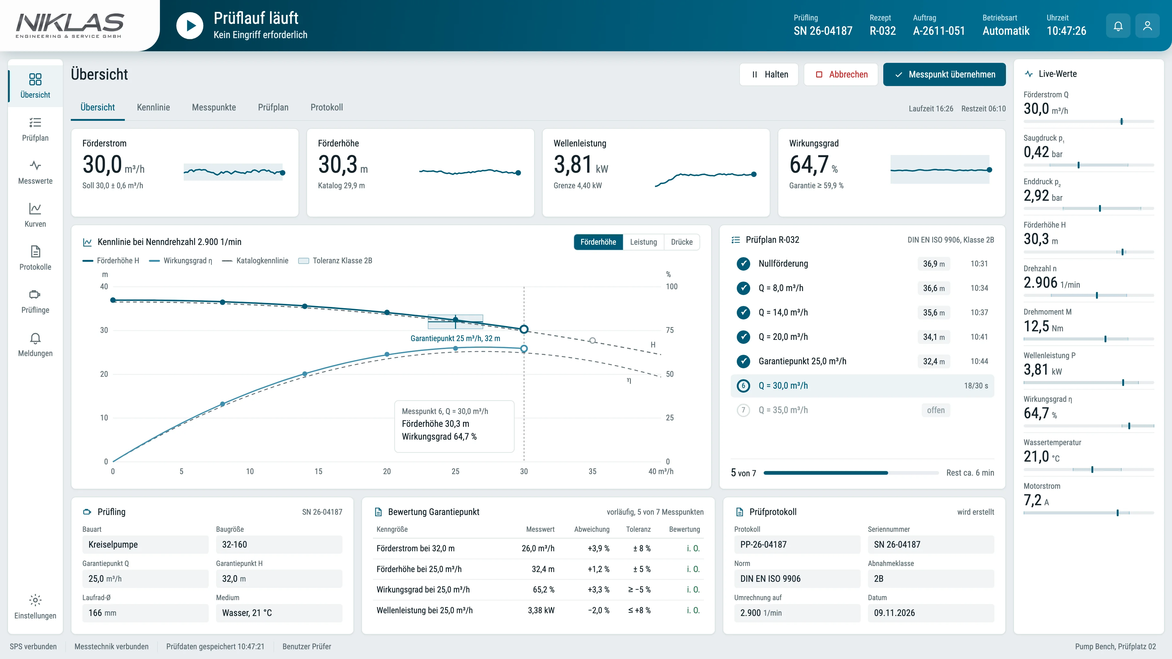
With the NIKLAS Pump Bench you measure flow rate, pressure, speed and shaft power for each operating point. The test software guides you through the test plan, shows the characteristic curve as a chart and creates the test report with serial number and test date for each pump.
Your own pump test bench or a testing service provider?
Your own pump test bench pays off if you test pumps regularly, the pumps have to go back to the customer quickly or you want to provide the proof yourself. With only a few tests a year or very large individual pumps, the test field of a service provider or manufacturer is often the better choice.
- In favour of your own test bench: recurring pump types, short lead time, testing of every repaired pump, comparison with earlier measurements of the same pump.
- In favour of a service provider: infrequent tests, pumps far beyond the power range of your operation, one-off acceptance tests to grade 1 with a customer representative.
What determines the effort and cost of a pump test bench?
| Cost driver | Why |
|---|---|
| Maximum drive power and speed range | Determine test motor, converter, mains connection and torque measuring shaft |
| Maximum flow rate and nominal sizes | Determine pipework, valves, flowmeters and tank size |
| Maximum head | Determines the pressure rating of pipework, valves and pressure sensors |
| Acceptance grade | Grade 1 needs more accurate sensors, torque measurement, longer pipe runs and regular calibration |
| NPSH test | Needs a closed tank, a vacuum pump and temperature control |
| Heat dissipation | With high power and long series of measurements, enlarge or cool the tank |
| Variety of pumps | Different designs and flanges need mountings and adapters |
| Degree of automation | Controlled throttle valve, stored test plans, automatic evaluation and report |
What to look for when buying a pump test bench
- Measurement uncertainty proven for each measured quantity and suitable for the required grade, with calibration certificates
- Shaft power measured via torque and speed if you verify efficiencies
- Head calculated with velocity head and the height of the measuring points
- Conversion to rated speed and evaluation at the tolerance cross in the software
- Test report with serial number, test conditions and characteristic curve
- Guarding of rotating parts and quick changeover between pump types
We design the NIKLAS Pump Bench for your pump types and your test specification: test circuit, drive, measuring equipment and mounting. What belongs in an enquiry is shown in our article Requirements specification for a test bench.
Frequently asked questions about pump testing to ISO 9906
Answers on acceptance grades, evaluation, test set-up and choosing a pump test bench.
Which acceptance grade do I need?
That depends on the application. For power plants and for oil and gas, 1B is common; for water supply up to 100 kW the standard specifies 2B, for solids-handling pumps 3B. Tighter grades need more accurate measuring equipment. Specify the grade in the purchase order.
What do B, U and E mean in the grades?
B stands for a tolerance upwards and downwards, U for a tolerance upwards only. E corresponds to grade 1B, but the efficiency must not fall below the guaranteed value.
Does the pump pass if only the flow rate or only the head is within tolerance?
Yes. The characteristic curve converted to rated speed only has to intersect or touch one of the two bars of the tolerance cross at the guarantee point.
May the test run at a different speed?
Yes. For flow rate, head and power, the standard permits 50 % to 120 % of the rated speed, and the values are converted with the affinity laws. For NPSH tests the speed should be between 80 % and 120 %.
Do I need a torque measuring shaft to verify efficiency?
For grade 1 it is the safe route. With torque and speed, the efficiency uncertainty is ±2.9 %, via motor power and motor efficiency ±3.2 %. With converter drives, the route via motor power is additionally uncertain.
Is a pump test bench of its own worthwhile for a repair shop?
Yes, if you regularly repair pumps of a similar size and want to verify every pump before delivery. You save transport and waiting time and can compare every pump with earlier measurements. With infrequent tests or very large individual pumps, an external test field is usually more economical.
What determines the effort for a pump test bench?
Above all the maximum drive power, the maximum flow rate with the nominal sizes, the maximum head and the required acceptance grade. Added to this are NPSH testing, heat dissipation, the number of pump types and the degree of automation of test plan and report.
Can a pump test bench later be extended for NPSH testing or larger pumps?
That is possible if tank, pipework and drive are designed for it from the outset. An open tank cannot simply be converted into a vacuum tank, and the nominal sizes limit the flow rate. So state planned extensions in your enquiry.
What information do you need for a quotation?
Pump types with design, connection sizes, weight and drive power, plus flow rates, heads, standard and grade, NPSH yes or no, test medium, tests per day and installation site with water and power connections. Rough information is sufficient; we will ask about anything missing.
More technical articles
Test engineering Test engineering
Test bench requirements specification
Test items, power, measurement uncertainty, cycle time, energy and acceptance with formulas and worked examples: what a requirements specification for a test bench must contain. Test engineering
AI vision inspection
Resolution, lens, exposure, sample parts, escapes and false rejects with formulas and worked examples: how to design an AI vision inspection and accept it.Enquire about a pump test bench
State pump types, flow rates, heads and the required acceptance grade. We will get back to you with a proposal for the test circuit and measuring equipment.
Simon Niklas
Mechanical engineer, M.Sc.
+49 941 56956720[email protected]
“Good engineering proves itself in day-to-day production. That is why we combine technical planning with a close understanding of process, operation and maintenance.”
Book a consultation