
NIKLAS Vision Check
Visual inspection system with AI evaluation for parts
With the NIKLAS Vision Check visual inspection system you inspect parts by camera for missing components, position, surface defects and codes. You set up new parts yourself, and locally operated AI models evaluate the images.
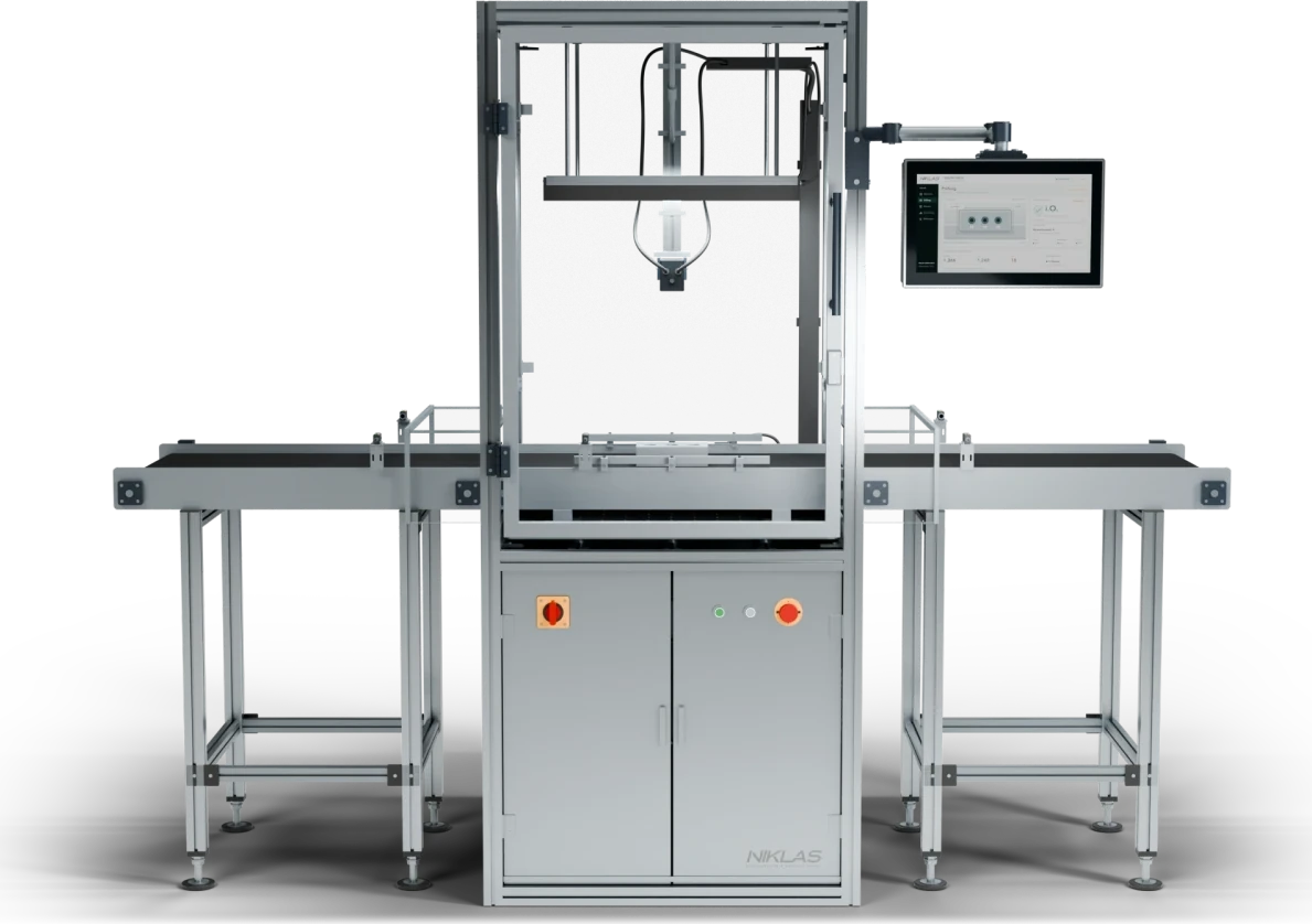
Visual inspection system as a stand-alone cell or inline
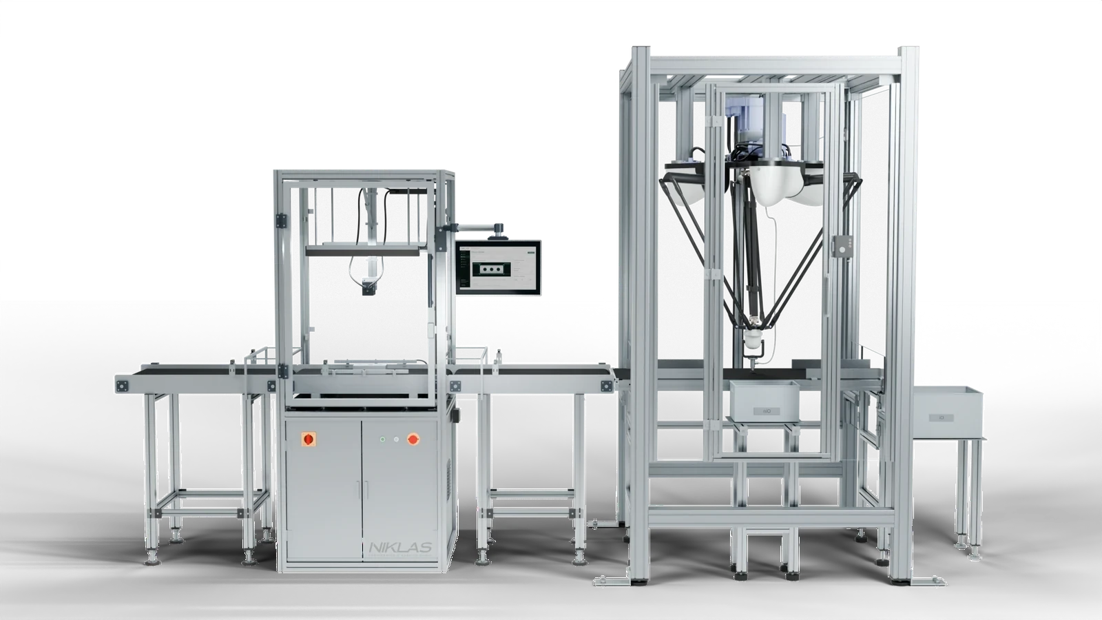
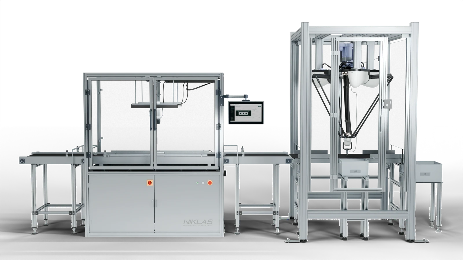
We adapt the visual inspection cell to your part sizes and your material flow. With a conveyor belt, Vision Check becomes an inline inspection system. An optional delta picker sorts the inspected good and bad parts.
- Directly in productionDetect deviations before the next work step
- Handles variantsCreate new parts yourself during operation
- OK or NOKDistinguish good and bad parts in the process
At a glance
Your parts, create new parts yourself
Missing parts, position, surface, codes
According to your inspection criteria
Stand-alone cell or inline with conveyor belt
Inspection image and inspection data for each part
According to part and cycle time
What the visual part inspection detects
Automated visual inspection with image processing, also called automated optical inspection or AOI for short, finds deviations before parts are processed further. We test in advance on your sample parts whether missing components, incorrect position, surface defects or labelling can be inspected on your part. We then design the camera, lighting and AI evaluation.
Missing components
Detect missing components on the part, provided that visibility, contrast and position allow an unambiguous evaluation.
Position and orientation
Check whether parts are positioned or installed correctly. The system compares them with reference images and defined position criteria.
Surface inspection
Detect scratches, damage and other visible deviations on suitable surfaces. Lighting and defect patterns determine the design.
Assembly and completeness
Check assemblies for visible assembly states and complete fitting before they move on to the next process step.
Labelling and codes
Check or read prints, markings or codes. Legibility and inspection method depend on the part and the labelling.
Contour and dimension
Check visible contours or dimensions, provided that resolution, perspective and calibration allow the required statement.
Holes and outlines
Check holes, punched-out areas and outlines as a silhouette in backlight, for example on injection-moulded plastic parts.
Deviations from the good part
Anomaly detection learns what a good part looks like and marks deviations, even without bad parts. It does not name a defect class.
Visual inspection: inspection tasks, lighting, resolution, verification
What can be inspected visually, why the light is decisive, how fine the image must be and how the inspection can be verified.
What can be inspected visually
The camera checks what is visible in the image and differs from the good part. This covers completeness, position, surface, dimensions and labelling.
The camera detects missing components, incorrectly inserted parts and incomplete fitting, provided that visibility, contrast and position allow an unambiguous evaluation. Concealed areas need an additional viewing angle.
The camera detects scratches, damage and other visible deviations if the lighting separates them from the good area. Textured or uneven surfaces are more demanding. We define with you at what point a deviation counts as a defect.
The camera checks dimensions if resolution, perspective and calibration support the tolerance. Telecentric lenses avoid perspective errors, and backlight delivers sharp outlines. We test in advance on your sample parts whether your tolerance can be achieved.
We check or read prints, markings and codes if the smallest structure has enough pixels. For 2D codes, at least 5 pixels per smallest module is the guide value. Contrast and lighting determine legibility.
Why the light decides what is detected
The evaluation only detects what has contrast in the image. Lighting and optics make the inspection feature visible before the evaluation assesses it.
The lighting determines whether a defect appears in the image. We select the camera, optics and lighting according to the feature and the surface.
With front light, the light source sits on the camera side. Dark field, meaning light at a shallow angle, makes scratches, edges and engravings appear bright on a dark background. Shiny, curved parts need diffuse light, otherwise the edges stay dark.
Backlight shows the part as a silhouette. It clearly shows holes, punched-out areas and outlines, for example on injection-moulded plastic parts. For tight dimensional tolerances, telecentric backlight is used.
Telecentric lenses keep the magnification constant, so height differences on the part do not distort the dimension. The front lens must be at least as large as the part. They do not have more depth of field than normal lenses.
How fine and how fast the image must be
Resolution and exposure time follow from the smallest defect and the part speed. We calculate both from your parts and your cycle time before we design the system.
The smallest defect should cover at least three pixels in the image. This is a rule of thumb from camera manufacturers, not a standard. Two pixels are considered the theoretical limit.
The required number of pixels per axis is the field of view divided by the defect size, times three. With a 200 mm field of view and a 0.1 mm defect, that is 6,000 pixels. If one sensor is not enough, a smaller field of view or a second image helps.
The lens must resolve the pixel size of the sensor, otherwise the image remains blurred. As a rule of thumb, you calculate with 3 to 4 pixels per smallest detail for colour cameras and 2 for monochrome cameras.
Moving parts need short exposure. At 0.5 m/s, a maximum of 2 pixels of blur and 0.025 mm per pixel, this is around 100 µs. Strobe lighting works with 10 to 750 µs and suppresses ambient light.
How to prove that the inspection is correct
An inspection result is valid once it has been proven on known parts. This includes error rates, a capability study and stored inspection data.
Slip means missed defects; false rejects are good parts reported as bad. An inspection process should keep both low. With many false rejects, someone has to recheck every hit by hand.
Whether a feature can be inspected becomes clear with good parts, bad parts and borderline cases. Bad parts are often scarce and rarely cover all defect types. We test in advance on your sample parts and agree borderline cases with you.
For visual inspections there are established methods for demonstrating capability, for example kappa statistics to AIAG MSA and VDA Volume 5. Which evidence is required depends on the risk classification and on your customer.
The inspection image and inspection data for each part can be documented and passed on to the downstream process. Where traceability is required, ISO 9001 section 8.5.2 requires the identification of the results and the retention of the necessary information.
More on this in the Knowledge article AI image inspection in final inspection.
Which features should the system detect?
Send us photos of your parts and typical defects. We tell you which camera, lighting and evaluation suit them.
AI-assisted inspection: when fixed rules are enough and when AI helps
Which evaluation is suitable depends on the feature. The Vision Check evaluates with locally operated AI models, and your team trains new variants on good and bad samples.
Clearly measurable features such as position, dimension or code can be described as rules. The result is traceable. With objects that cannot be captured in rules, rules reach their limits.
Anomaly detection learns what a good part looks like and marks deviations. It does not need bad parts, but does not name a defect class.
If you want to name defect types, the model learns from examples for each class. If bad parts are missing or defect types are under-represented, detection suffers. Labelling the images is time-consuming and often leads to inconsistencies.
An AI detects what its training images cover. If lighting, batch or process change, detection should be checked again.
Inspecting and sorting in one system
With a conveyor belt and optional delta picker, we integrate NIKLAS Vision Check into your production line as a visual inspection and sorting system. The inspection cell assesses the defined features; OK and NOK parts then continue separately. We define the design according to the part, defect pattern and cycle time.
The conveyor belt feeds the parts into the inspection cell. We define the usable belt width, transfers and guidance to suit the part format and material flow.
We select the camera, optics and lighting according to the features and surfaces to be detected. This way the system captures each part under the same conditions.
After the initial set-up, your team creates new parts and inspection recipes itself via the user interface. Suitable sample images form the basis for the AI-assisted evaluation.
The delta picker picks up inspected parts and places them at defined outputs. We design the gripper, reach and cycle time for your part.
The illustration shows separate output areas for OK and NOK parts. How the parts are handled afterwards depends on your process.
Via an interface, your PLC or higher-level system receives the inspection decision and the inspection data. The next process step then responds to OK or NOK.
Setting up new parts within your own team
With the NIKLAS Vision Check software, your team creates new parts and inspection recipes itself. The interface shows the inspection task and decision at a glance. Locally operated AI models evaluate the images according to the defined features.
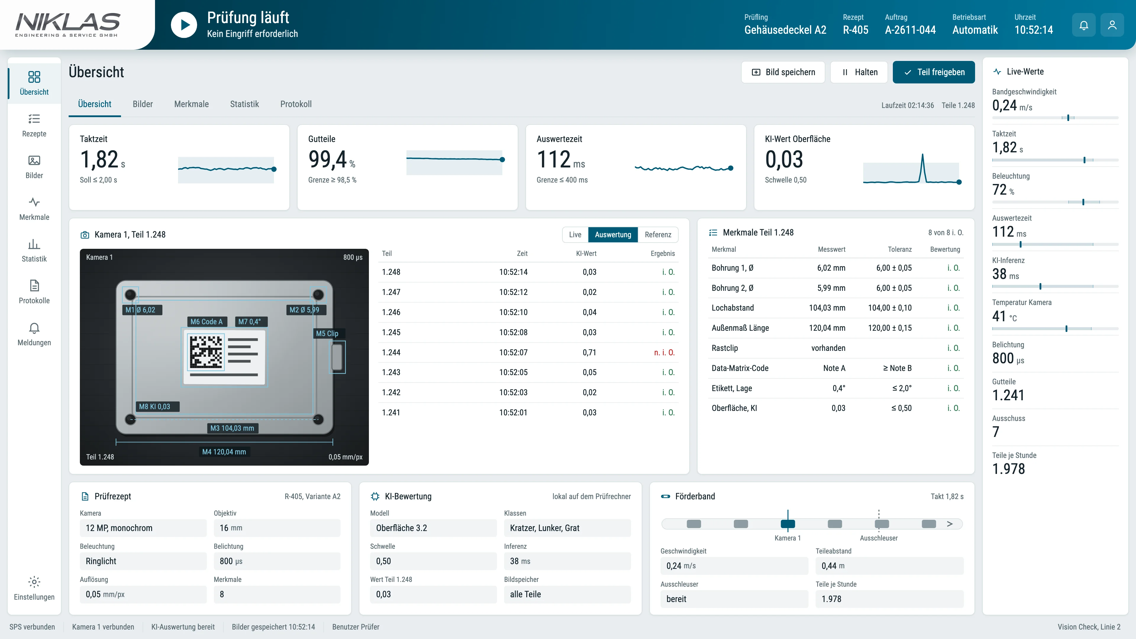
Interface and functions depend on the version.
Managing inspection programs yourself
When changing parts, your team selects the stored inspection program and can continue inspecting immediately.
Your team trains new variants itself with suitable good and bad samples. We define together during the design which defect patterns the evaluation should detect.
Inspection decisions and inspection data are documented for each part and can be passed on to the downstream process.
Frequently asked questions about the visual inspection system
We answer questions about the inspection scope, setting up new parts, stand-alone cells and inline systems. We clarify the suitability of your part in advance using sample parts.
What is a visual inspection system?
A visual inspection system automatically inspects parts by camera according to defined criteria and shows directly whether a part is OK or not OK, also called NOK. The Vision Check evaluates the images with locally operated AI models.
How many pixels does a defect need for the camera to detect it?
As a rule of thumb, three pixels across the smallest defect. Two pixels are the theoretical limit.
Which lighting is suitable for surface defects?
Usually dark field: light at a shallow angle makes scratches and edges appear bright. Shiny, curved parts need diffuse light.
When is AI better than fixed rules in image processing?
When the inspection criterion cannot be described as a fixed rule, for example on uneven surfaces. For unambiguous features such as position, dimension or code, rules are often sufficient.
Can a camera also check dimensions?
Yes, if resolution, perspective and calibration support the tolerance. Telecentric lenses and backlight deliver the more precise edges.
How do you prove that a visual inspection is suitable?
With a capability study on reference parts, for example with kappa statistics to VDA Volume 5. Which evidence is required depends on the risk classification and on your customer.
How does your own team set up new parts?
After the initial set-up, your team creates new parts and inspection recipes itself via the user interface and trains new variants with suitable good and bad samples. We agree the inspection criteria and borderline cases with you during the initial design.
What information helps for a quotation?
Describe your parts and which defects are to be detected and, if known, the cycle time, available space and feeding. We get back to you personally within 4 working hours.
Discuss a visual inspection system for your inspection task
Describe the part, inspection features and quantity. We are also happy to discuss unusual parts. We get back to you with a proposal for the set-up and sequence.

Simon Niklas
Mechanical engineer, M.Sc.
+49 941 56956720[email protected]
“Good engineering proves itself in day-to-day production. That is why we combine technical planning with a close understanding of process, operation and maintenance.”
Book a consultation