
 Test engineering
Testing services
Test report to DIN EN 60204-1 (VDE 0113-1): tests, limit values and structure
A test report to DIN EN 60204-1 (VDE 0113-1) documents the tests from clause 18 on the electrical equipment of a machine: comparison with the documentation, continuity of the protective conductor, disconnection conditions, insulation, voltage test, residual voltage and function. For each test point it records the measured value, the requirement and the evaluation, together with the machine, the revision of the circuit diagrams, the measuring instruments, the tester and the date. Without a product standard, the comparison with the documentation, protective conductor continuity, the functional test and, with automatic disconnection, its conditions must always be tested.

What must a test report to EN 60204-1 contain?
The test report names the machine tested, the revision of the documents, every test to clause 18 with measured value and requirement, the evaluation, the defects as well as the tester and the date. The standard requires the results to be documented. A required value next to each measured value makes the evaluation traceable for third parties.
This is how we structure a report, in the order of the tests:
| Element | Clause | What you enter | Requirement |
|---|---|---|---|
| Header | general | Machine with type, serial number, year of manufacture, location; revision of the circuit diagrams; edition of the standard; measuring instruments with calibration status; tester, date | complete |
| Comparison with documentation | 18.1 a) | Deviations between equipment and circuit diagram, visual inspection | Equipment matches the documentation |
| Protective conductor continuity | 18.2.2 | Test point, test current, measured value, expected value | within the expected range |
| Disconnection condition | 18.2.3 | Protective device, disconnection current, measured loop impedance | Zs ≤ U0 / Ia |
| Insulation resistance | 18.3 | Test voltage, measured value, disconnected components | at least 1 MΩ at 500 V DC |
| Voltage test | 18.4 | Test voltage, duration, disconnected components | no breakdown |
| Residual voltage | 18.5 | Measuring point, voltage after 5 s or 1 s | 60 V maximum |
| Protective conductor current above 10 mA | 18.1 g) | Measure taken according to 8.2.6 | requirements met |
| Functional test | 18.6 | Emergency stop, safety doors, interlocks, control functions | functions as specified |
| Result | general | Defects with corrective action, overall result, name and signature | released or not |
If the test also counts as an inspection under Section 14 of the German Industrial Safety Regulation (BetrSichV), the record must contain at least the type of inspection, the scope, the result and the name and signature of the person qualified to carry out the inspection. It is kept at least until the next inspection.
Which tests does clause 18 of EN 60204-1 require?
Clause 18 lists eight tests, from a) to h). If there is a product standard for the machine, it defines the scope. Without a product standard, the comparison with the documentation, protective conductor continuity, the functional test and, with protection by automatic disconnection, its conditions must always be carried out; the other tests are added depending on the machine.
| Item | Test | Without product standard |
|---|---|---|
| a) | Conformity with the technical documentation | always |
| b) | Continuity of the protective bonding circuit (test 1) | always |
| c) | Conditions for protection by automatic disconnection of supply (test 2) | always, if this fault protection is used |
| d) | Insulation resistance | depending on the machine |
| e) | Voltage test | depending on the machine |
| f) | Protection against residual voltage | depending on the machine |
| g) | Requirements for protective conductor currents above 10 mA | depending on the machine |
| h) | Functional tests | always |
The standard recommends testing in this order. One point is mandatory: you test protective conductor continuity before the loop impedance, because with an interrupted protective conductor the loop measurement can make the enclosure live. In practice we also measure the insulation before the voltage test, so that a gross insulation fault does not first show up under high voltage.
Clause 18 covers testing at installation and after modifications (18.7). Periodic testing during operation follows DIN VDE 0105-100, DGUV V3, the German accident prevention regulation for electrical installations and equipment, and the intervals from your workplace risk assessment. The report of the initial verification is the most important basis for comparison.
How do you measure protective conductor continuity and which value is acceptable?
The resistance is measured between the protective conductor terminal at the supply and every relevant point of the protective bonding circuit, with a current between 0.2 A and about 10 A from a separate source with a maximum no-load voltage of 24 V. The standard does not give a fixed limit value: the measured value must be within the expected range, which you calculate from the length, cross-section and material of the protective conductor.
R = ρ · lA
- R
- expected resistance of the protective conductor in Ω
- ρ
- resistivity, for copper at 20 °C about 0.0178 Ω·mm²/m
- l
- conductor length from the measuring point to the protective conductor terminal of the supply in m
- A
- cross-section of the protective conductor in mm²
Example: A motor is connected to the control cabinet via 30 m of cable with a 2.5 mm² protective conductor. The expected value is 0.0178 · 30 / 2.5 = 0.21 Ω. A measured value of 0.24 Ω fits; terminal points explain the difference. If the instrument shows 0.03 Ω, the current probably flows through a parallel path, for example through the machine frame or cable tray, and the protective conductor itself remains untested (example values).
Guide values for copper at 20 °C, calculated with the resistivity from the formula. Fine-stranded conductors are slightly higher according to IEC 60228.
| Cross-section | 1.5 mm² | 2.5 mm² | 4 mm² | 6 mm² | 10 mm² | 16 mm² | 25 mm² |
|---|---|---|---|---|---|---|---|
| Resistance per metre | 11.9 mΩ | 7.1 mΩ | 4.5 mΩ | 3.0 mΩ | 1.8 mΩ | 1.1 mΩ | 0.71 mΩ |
Typical measuring errors and how to avoid them:
- Test leads not zeroed: Zero the test leads before measuring or measure with four-wire technology. With small values the leads otherwise make up the largest part.
- Paint and coating: Place the test probe on bare metal, not on painted surfaces.
- Parallel paths: A conspicuously small value is not a good sign. If in doubt, disconnect the connection and measure the conductor on its own.
- Test current too low: Higher currents improve accuracy with large cross-sections and short conductors. Many instruments offer 10 A or more for this.
How do you check the disconnection condition via the loop impedance?
The disconnection condition is met if the fault loop has such a low impedance that the fault current trips the protective device within the required time. In a TN system, the condition below applies. It is measured with an instrument to IEC 61557-3 at the mains frequency of the supply.
Zs · Ia ≤ U0
- Zs
- impedance of the fault loop in Ω
- Ia
- current that trips the protective device within the required time, in A
- U0
- nominal voltage line to earth, 230 V in a 400/230 V network
Example: A C16 miniature circuit breaker trips instantaneously with certainty at 10 · 16 A = 160 A. This gives Zs ≤ 230 V / 160 A = 1.44 Ω. With the two-thirds reduction for conductor heating, the measured value should be below 0.96 Ω. The measurement shows 0.62 Ω: the condition is met. For a B16 with 80 A the values would be 2.88 Ω and 1.92 Ω (example values).
There is a reason for the reduction: the measurement is taken cold and with a small current, whereas in the event of a fault the conductors are warm and have a higher resistance. Annex A of EN 60204-1 therefore refers to a more precise evaluation according to IEC 60364-6 if the measured value is above two thirds of U0 / Ia. The required disconnection times are also given in Annex A and follow DIN VDE 0100-410: in a 230 V TN system, 0.4 s for final circuits up to 32 A and up to 5 s for distribution circuits.
- Where to measure: at the supply terminals of the machine and at the final circuits, in each case between line conductor and protective conductor.
- Calculating instead of measuring: If calculations of the loop impedance are available and length and cross-section can be verified, the continuity test may replace the measurement. Table 10 of the standard gives examples of permissible cable lengths.
- Frequency converters: Downstream of converters the loop measurement is not meaningful. What counts there is the fault protection provided by the converter manufacturer.
- Residual current devices: You test their function according to the manufacturer’s instructions and enter the result.
Which test voltage and which limit value apply to the insulation measurement?
The insulation measurement to 18.3 applies 500 V DC between the conductors of the power circuits and the protective bonding circuit. The insulation resistance must be at least 1 MΩ. For parts such as busbars, conductor rail systems or slip ring assemblies, a minimum value of 50 kΩ applies.
1 MΩ at 500 V corresponds to a fault current of 0.5 mA. In practice intact machines are well above this, often in the range of many MΩ to GΩ. A value just above 1 MΩ formally passes, but it is a reason to look for moisture, dirt or cable damage.
- Surge protection: Disconnect surge arresters that could respond at 500 V DC, or reduce the test voltage below their protection level, but not below the peak value of the upper limit of the supply voltage line to neutral.
- Electronics: Disconnect frequency converters, power supplies and filters according to the manufacturer’s instructions or short-circuit their inputs. Note in the report what was disconnected.
- Measuring in sections: If the installation cannot be measured as a whole, you may test individual sections.
- After the measurement: Long cables and motors remain charged. Discharge them before you reconnect anything.
You can read more about insulation measurement on windings, the PI value and temperature correction in our article Measuring motor windings.

Which test voltage applies to the voltage test to 18.4?
In the voltage test, an AC voltage at 50 or 60 Hz is applied for about 1 s between the conductors of all circuits and the protective bonding circuit. The test voltage is twice the rated voltage of the supply or 1,000 V, whichever is greater. The test is passed if no breakdown occurs.
| Rated voltage of the supply | 230 V | 400 V | 480 V | 690 V |
|---|---|---|---|---|
| Test voltage | 1,000 V | 1,000 V | 1,000 V | 1,380 V |
The test equipment complies with IEC 61180. PELV circuits are excluded from the test. Disconnect components that cannot withstand the test voltage; components that have already been voltage-tested to their product standard may be disconnected.
A common pitfall: interference suppression filters with capacitors to the protective conductor draw a capacitive current under AC voltage. The tester then switches off due to overcurrent, although there is no breakdown. A test plan that defines which components are disconnected, which contactors are closed and where the voltage is applied prevents wrong evaluations. Test within the interlocked test area; what a test station needs for this is set out in our checklist for test stations to DIN EN 50191.
How do you test protection against residual voltage (60 V in 5 s)?
Live parts with a residual voltage above 60 V must be discharged to 60 V or less within 5 s after switching off (6.2.4). For plugs whose pins are exposed after withdrawal, 1 s applies. Components with a stored charge of no more than 60 µC are exempt.
To measure, switch off the supply and record the voltage at the critical points, for example at the DC link of a converter or at capacitor banks. An instrument with recording function or an oscilloscope shows the curve. You can calculate in advance how quickly a capacitor discharges as follows:
t = R · C · ln U060 V
- t
- time until 60 V in s
- R
- resistance of the discharge path in Ω
- C
- stored capacitance in F
- U0
- voltage at switch-off in V
Example: A converter on a 400 V network has a DC link with around 565 V DC and 1,000 µF. Via an internal discharge resistor of 100 kΩ it takes 100 kΩ · 1,000 µF · ln(565 / 60) = 224 s, almost 4 minutes, to reach 60 V. For 5 s the resistor would have to be below 2.2 kΩ and would continuously dissipate around 140 W during operation (example values).
The example shows why converters often do not meet the 5 s. If rapid discharge would interfere with the function, the standard requires a permanent warning notice in a clearly visible position on the enclosure that draws attention to the hazard and states the waiting time before opening. Check whether this notice is present and enter the waiting time in the report.
The 60 µC exemption helps with small capacitors: the charge is capacitance times voltage, so at 565 V 60 µC corresponds to around 0.1 µF. Interference suppression capacitors are often below this, DC links almost never.
What is part of the functional test and of retesting after modifications?
The functional test to 18.6 tests the functions of the electrical equipment, especially the safety-related ones. After a modification you retest the modified part to 18.7 and check whether the modification affects other parts, for example through overstressing of the insulation.
- Emergency stop: trigger every emergency stop device, check the stop category and restart. After resetting, the machine must not start by itself.
- Safety doors and guard locking: opening during movement, release only in the safe state.
- Electro-sensitive protective equipment: function and stopping time, because the stopping time determines the safety distance according to DIN EN ISO 13855.
- Control functions: operating modes, end positions, monitoring functions such as earth fault or insulation monitoring.
Typical reasons for retesting are work on protective conductors, overcurrent protection or insulation, new drives and changes to the safety controller. If the modification goes so far that new hazards arise, it can be a substantial modification; manufacturer obligations then apply, up to CE marking.
Create the test report yourself, automate it with software or commission it?
That depends on whether you build or operate machines. If you build control cabinets or machines in series, you automate the test at the test station and generate the report for each serial number. If you operate machines, you usually have the test carried out by a qualified electrician with suitable measuring equipment, in-house or as a service.
In practice the test is carried out by a qualified electrician with experience in machine testing and suitable measuring equipment. Inspections under Section 14 BetrSichV require a person qualified to carry out inspections, with vocational training, professional experience and recent professional activity (Section 2 (6) BetrSichV). For the initial verification, the manufacturer or installer is usually responsible.
| Your situation | What works well | What we offer |
|---|---|---|
| Series production of control cabinets or machines | Fixed test station, test sequence with limit values, report for each serial number | NIKLAS Test Field with test software |
| Final testing with rework and traceability | Versioned test plans with approval, rework under the same serial number | NIKLAS Safety One, new for 2027 |
| Existing machines, testing after modification | On-site testing with an inspection report for each machine | DGUV V3 inspection with testing to EN 60204-1 |
The NIKLAS Test Software guides you through the sequence, evaluates every measured value against its limit values and stores serial number, test date and measured values in the test report; you transfer the test data to your ERP system via an interface. Safety One tests high voltage, insulation and protective conductor in one device and exports as CSV, JSON or PDF.
To test existing machines, we need a machine list with manufacturer, year of manufacture and location, existing circuit diagrams and test reports, and your downtime window. We classify defects by severity, quote a fixed price for rectifying them and update the circuit diagrams after modifications.
Frequently asked questions about the test report to EN 60204-1
Answers on scope, measured values and delimitation. Clarify before testing which edition of the standard and which product standard apply to your machine.
Is a test report to EN 60204-1 mandatory?
Yes. Clause 18 requires the results of the tests to be documented. The report is also part of the technical documentation of the machine and the basis for comparison in later periodic tests.
Which limit value applies to the protective conductor resistance?
The current standard does not give a fixed limit value. The measured value must match the length, cross-section and material of the protective conductor. Calculate the expected value from resistivity, length and cross-section and enter it next to the measured value.
Which test current is used to measure the protective conductor?
A current between 0.2 A and about 10 A from a separate source with a maximum no-load voltage of 24 V. Higher currents give more accurate values with large cross-sections and short conductors.
What is the difference between testing to EN 60204-1 and the DGUV V3 inspection?
Clause 18 of EN 60204-1 describes testing at installation and after modifications. Periodic testing during operation follows DGUV V3, the German accident prevention regulation for electrical equipment, DIN VDE 0105-100 and Section 14 of the German Industrial Safety Regulation (BetrSichV), with intervals from your workplace risk assessment. Measurements and report structure are similar; the values of the initial verification serve as a comparison.
Who may carry out the test to clause 18?
A qualified electrician with experience in testing machines. For the initial verification, the manufacturer or installer is usually responsible. Inspections under Section 14 BetrSichV are carried out by a person qualified to carry out inspections.
Can the test report be generated automatically with software?
Yes. At the test station, the NIKLAS Test Software guides you through the sequence, evaluates measured values against limit values and stores them in the test report for each serial number. You transfer the data to your ERP system via an interface. We define with you which fields the report needs.
What does a machine inspection with test report cost?
That depends on the number, age and equipment of the machines and on the condition of the documentation. Based on your machine list, we quote a fixed price per machine or test package.
Do you also test older machines without complete circuit diagrams?
Yes. If documents are missing, we record the actual condition on site. You can only tick off the comparison with the documentation once the circuit diagram and machine match; after modifications we update the circuit diagrams.
More technical articles
Test engineering Retrofit
PLC migration to S7-1500
Failure risk, data backup, I/O reserve, cycle time, program conversion, safety technology and signal test: how a PLC migration to S7-1500 or Beckhoff becomes plannable and what determines the effort.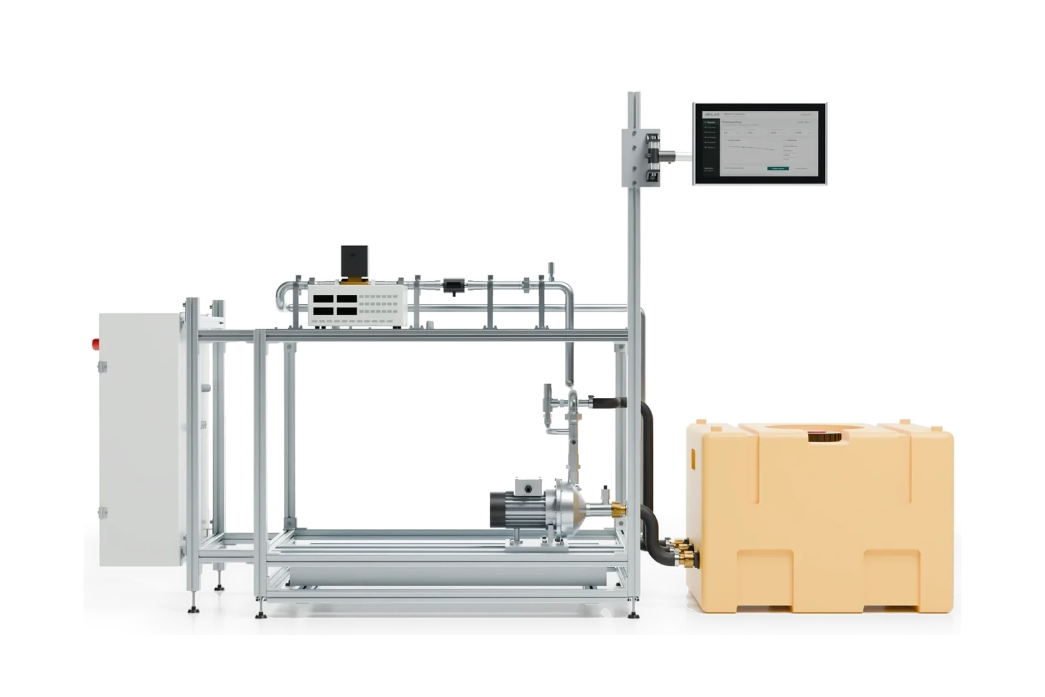 Test engineering
Pump testing ISO 9906
Tolerances of grades 1B, 2B and 3B, head and efficiency with a worked example, measurement uncertainty, NPSH3 and test procedure: how a pump test to DIN EN ISO 9906 runs on the test bench.Enquire about machine testing or a test station
Send us a machine list with manufacturer, year of manufacture and location as well as existing circuit diagrams and test reports. For a test station, state the test item, test voltage and quantity. We will get back to you with a proposal for scope and date.
Simon Niklas
Mechanical engineer, M.Sc.
+49 941 56956720[email protected]
“Good engineering proves itself in day-to-day production. That is why we combine technical planning with a close understanding of process, operation and maintenance.”
Book a consultation