
 Test engineering
Testing industrial gearboxes after repair: load test, efficiency and vibration
A repaired industrial gearbox should run under load before it is installed. Only under load do the tooth flanks make contact, do bearings and oil reach operating temperature, and do faults in the contact pattern, bearing adjustment or seals become measurable. If you also measure torque and speed on both shafts, you can prove the efficiency.

Is a no-load run enough after a gearbox repair?
For gross assembly errors, yes; for a statement about operation, no. A no-load run shows the direction of rotation, noise, first temperatures and tightness. Contact pattern, bearing adjustment and vibration behaviour only show up under load, when the tooth flanks make contact and the bearings and housing heat up as in operation.
Only under load do the following become visible:
- a contact pattern that runs towards the tooth edge because shafts or bearing bores are not aligned
- too much preload on tapered roller bearings, which only builds up with heat
- gear mesh and bearing frequencies in the vibration spectrum that are lost in the noise at no load
- leaks that only occur with warm, thin oil
- blocked oil bores or incorrectly fitted seals, which show up as a rise in temperature
In helical gearboxes, the axial force reverses with the direction of rotation. If the gearbox runs in both directions in operation, the load test must cover both directions.
How do you measure the efficiency of a gearbox?
You measure torque and speed at the input and output shaft, calculate both powers from them and divide the output power by the input power. The difference is the power loss, which turns into heat in the gearbox. Power follows from torque and speed:
P = 2 · π · n · M60
- P
- shaft power in W
- n
- speed in 1/min
- M
- torque in N m
Example: 1,000 N m at 1,500 1/min on the input give 157.1 kW.
For efficiency, gear ratio and power loss:
η = PoutPin = Mout · noutMin · nin = Mouti · Min i = ninnout Ploss = Pin − Pout
- η
- gearbox efficiency (dimensionless, usually given in %)
- Pin, Pout
- power at the input and output shaft in W
- Min, Mout
- torque at the input and output shaft in N m
- nin, nout
- speed at the input and output shaft in 1/min
- i
- gear ratio (dimensionless), equal to the ratio of the numbers of teeth for gear units
- Ploss
- power loss in W, which turns into heat in the gearbox
Example: Gear ratio 5, so 300 1/min at the output, measured torque 4,850 N m. The output power is 152.4 kW, the efficiency 4,850 divided by 5,000, so 97.0 %. The power loss is 4.7 kW.
In gear units the gear ratio is fixed by the numbers of teeth; there is no slip. The speed measurement therefore contributes hardly anything to the error; what matters is the measurement of the two torques. The speeds serve mainly as a check: if the measured ratio deviates from the gear ratio, something is wrong with the measurement.
The losses arise in the gearing, bearings, seals and from churning in the oil. One part grows with the torque; the load-independent part also occurs at no load. At low load the efficiency is therefore significantly worse than at rated load. Always compare efficiencies at the same load, speed and oil temperature.
For orientation: one manufacturer states a mechanical efficiency of at least 96 % for a two-stage bevel geared motor and 94 % for a three-stage version. So every stage costs efficiency; worm gearboxes are well below that.
Why do small torque errors distort the gearbox efficiency?
Because the power loss is a small difference between two large powers. At 97 % efficiency the losses are only 3 % of the input power, but any error in either of the two torques goes fully into these 3 %. A measurement error of 0.5 % can already distort the losses by one third.
Δη ≈ η · (|δin| + |δout|) ΔPlossPloss ≈ Δη1 − η
- Δη
- largest deviation of the measured efficiency (worst case)
- δin, δout
- relative measurement deviation of the torques at input and output, relative to the measured value
- ΔPloss / Ploss
- relative deviation of the calculated power loss
Example: If, in the example, the input transducer reads 0.5 % too low and the output transducer 0.5 % too high, the test bench measures 98.0 % instead of 97.0 % and 3.2 kW instead of 4.7 kW of loss. The losses are one third too small. With 0.1 % per transducer, the result is 97.2 % and 4.4 kW.
In addition, many manufacturers relate the accuracy class of a torque transducer to the rated torque of the transducer, not to the measured value. For a class 0.05 transducer with 1,000 N m rated torque, 0.05 % corresponds to a deviation of 0.5 N m, at every measured value. At 250 N m test torque that is 0.2 % of the measured value, four times as much as at rated torque.
How to avoid measurement errors in efficiency
- Choose the measuring range of the transducers according to the actual test torque; for a wide range, provide two transducers or two measuring ranges
- Install the transducers directly on the gearbox so that no bearings, couplings or intermediate shafts are included in the measurement
- Zero the transducers in the torque-free state before each series of measurements
- Only measure after running-in and at a steady oil temperature, because viscosity and churning losses change with temperature
- Calibrate the transducers regularly and file the calibration certificate with the test report
Efficiency is therefore mainly suited for comparison: between gearboxes of the same type, before and after repair, on the same test bench.
Brake, back-to-back or regenerative load: which gearbox test bench is right?
The gearbox needs a counter-torque at the output. Common options are a brake, a mechanical back-to-back arrangement of two gearboxes or a regenerative load machine. For repairers with changing gearbox types, regenerative load is usually the most flexible solution.
| Principle | How it works | Energy | Suitable for |
|---|---|---|---|
| No-load test bench | Drive without counter-torque | no-load losses only | Functional test, tightness, gross assembly errors |
| Brake | Eddy current, water or friction brake at the output | test power turns into heat | simple load test, low powers |
| Mechanical back-to-back | Two gearboxes braced against each other in a closed loop, the power circulates | drive only covers the losses | series of identical gearboxes, needs a second gearbox and suitable adapters |
| Regenerative load | Drive machine and load machine with converters, torque freely controllable | with energy recovery to the grid, essentially only the losses | changing gearbox types, load steps, efficiency |
With regenerative load, the output power is produced as electrical energy. It flows back via a common DC link of the converters or a regenerative converter. The energy balance shows the difference from the brake:
Pgrid ≈ PinηD − Pout · ηL
- Pgrid
- power that the test bench draws from the grid with energy recovery, in W
- ηD
- efficiency of the drive machine and converter together
- ηL
- efficiency of the load machine and converter together
Example: Assuming 93 % on the drive and load side, the drive in the example draws 168.9 kW from the grid and 141.7 kW flow back. Net, the test bench draws around 27 kW. With a brake it would be 168.9 kW, of which a good 152 kW would end up as heat in the cooling water.
On a back-to-back test bench, the drive covers the losses of both gearboxes in the loop, so around twice 4.7 kW in the example. For this, gear ratio and design must match, and the efficiency of a single gearbox can only be stated with assumptions about the second gearbox.
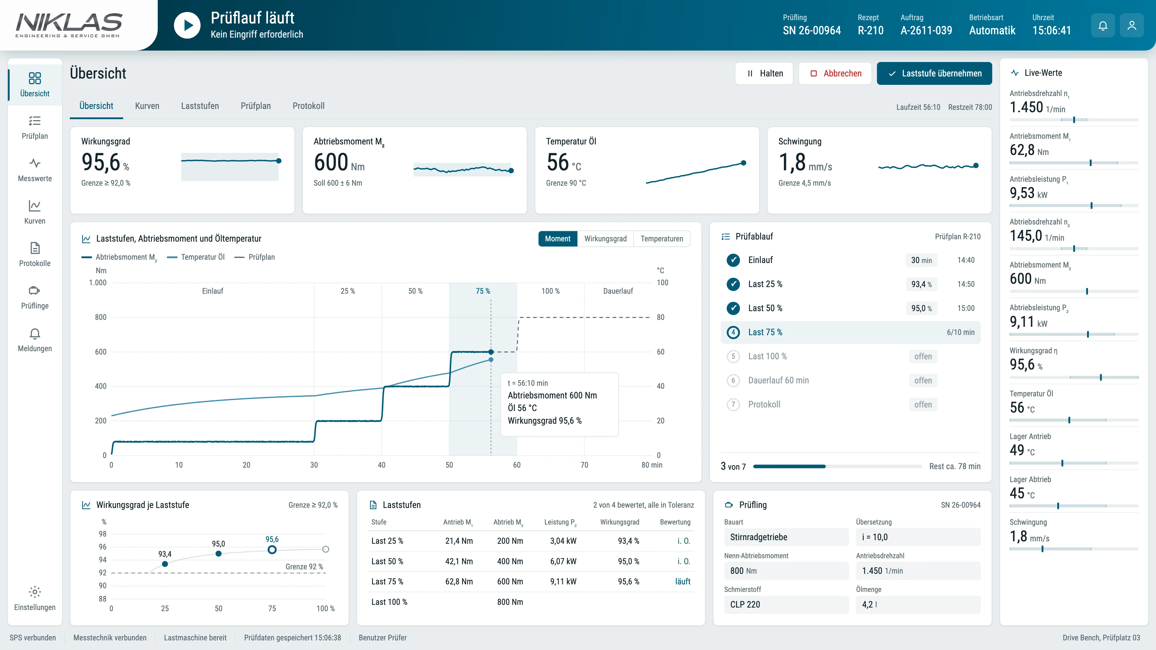
Our NIKLAS Drive Bench works with a drive machine and a regenerative load machine and measures torque and speed at two measuring points close to the gearbox, before and after it.
How does gearbox testing after repair work?
The test follows a fixed order: check before the run, no-load run, load steps up to the test load, endurance run until the temperature is steady, and oil change. This way the gearbox is loaded step by step and the measured values remain comparable between gearboxes.
- Before the run: visual inspection, backlash and bearing clearance to the manufacturer's specification, contact pattern without load as a first check, oil type, oil level and cleanliness of the fill.
- Clamping: place the gearbox in the matching fixture, align the shafts to the drive and load machine, fasten the torque arm or foot without stress.
- No-load run: start at low speed, then up to rated speed, both directions of rotation. Record no-load torque, noise and first temperatures.
- Load steps: increase the load step by step, for example in steps of 25 % up to the agreed test load. Record torque, speed, temperature and vibration for each step.
- Endurance run: at test load until oil and bearing temperatures are steady. Then measure efficiency and vibration for acceptance.
- Contact pattern under load: with a thin marking compound on the flanks of one gear, check and photograph after a load step with a short running time.
- After the run: check tightness, inspect the magnetic plug, drain the oil, flush and refill or change the filter. Otherwise the running-in debris goes to the customer too.
How do you assess the contact pattern?
The contact pattern shows where the tooth flanks bear on each other under load. The aim at test load is an even contact pattern across the face width and tooth height, with no hard contact at the tip, root or tooth ends. If the gear bears only at one end, shafts or bearing bores are not aligned, or the flank modification does not suit the load. A contact pattern without load is a first check; only the contact pattern under load is conclusive, because shafts and housing deform under load.
On the magnetic plug, a fine grey coating counts as normal wear debris. Coarse chips or glittering flakes indicate damage to the gearing or bearings.
Which temperature and vibration values apply to gearboxes?
The gearbox manufacturer specifies the permissible oil and bearing temperatures; what matters is the steady-state value under test load. Vibration acceptance of gearboxes is covered by ISO 20816-9, published in Germany as DIN ISO 20816-9:2021-03. Agree before the test which zone applies as the acceptance criterion.
Temperature and steady state
If the oil temperature keeps rising at constant load, speed and ambient temperature, something is wrong with the bearing adjustment, lubrication or cooling, and the run is stopped. ISO/TR 14179-1 calculates the thermal power capacity of gearboxes with an oil sump temperature of 95 °C at 25 °C ambient. There is no general value for the steady state of gearboxes. For electric motors, IEC 60034-1 defines thermal equilibrium as a change of at most 2 K per hour; you can agree a similar criterion for the endurance run.
Vibration to ISO 20816-9
ISO 20816-9 replaces the withdrawn ISO 8579-2. It applies to gearboxes from 10 kW to 100 MW and 30 to 12,000 1/min and evaluates broadband values of housing and shaft vibration in zones A to D. For acceptance at the plant, it requires operation within the design values for speed, load, temperature and lubrication. It does not evaluate run-up, run-down, load changes or torsional vibration.
The overall value is not enough for gearing and bearing damage. For that you need a spectrum in which you can find the gear mesh frequency and its sidebands:
fz = z · n60
- fz
- gear mesh frequency in Hz
- z
- number of teeth of the gear in question
- n
- speed of this gear in 1/min
Example: A pinion with 23 teeth at 1,500 1/min produces a gear mesh frequency of 575 Hz. The shaft rotational frequency is 25 Hz, so sidebands lie at 550 and 600 Hz.
| Finding in the spectrum | Common cause |
|---|---|
| High gear mesh frequency and harmonics at all load steps | Gear wear, misalignment, unfavourable contact pattern |
| Sidebands spaced at the shaft rotational frequency | Runout error, eccentric gear, damaged tooth on this shaft |
| Increased 1x shaft rotational frequency | Unbalance or misalignment to the drive or load machine |
| Bearing frequencies and their harmonics | Bearing damage, incorrect bearing preload |
Measure the vibration at a steady temperature and at the same measuring points as in earlier tests. Only then can values be compared between gearboxes and over time.
What belongs in the test report of a gearbox test?
The test report must show what was tested, under which conditions and with what result. Only then can a test later be compared with the next one.
- Gearbox with type, serial number, gear ratio, oil type and fill quantity
- Test sequence with speeds, load steps, directions of rotation and duration of each step
- Torque and speed at input and output, no-load torque, efficiency for each load step with oil temperature
- Oil and housing temperatures with their curve up to steady state
- Vibration values with measuring points, measuring direction and evaluation basis
- Contact pattern without and under load as a photo
- Tightness, finding on the magnetic plug, oil change after the run, tester and date
With the NIKLAS Test Software, these values are stored in one place for each gearbox, with serial number and test date. Running-in, load steps and endurance run run as a stored test plan.
Your own gearbox test bench or testing by a service provider?
Your own gearbox test bench pays off if you repair gearboxes regularly and want to prove every gearbox under load before delivery. For infrequent tests or very large one-off gearboxes, an external test bench is usually more economical.
What determines the effort and cost of a gearbox test bench?
The biggest cost driver is often underestimated: the output torque. The load machine must absorb the torque at the slow output, and this grows with the gear ratio.
Mout = Min · i · η
- Mout
- torque that the load machine must absorb, in N m
- Min
- input torque in N m
- i
- gear ratio
- η
- gearbox efficiency
Example: 250 N m at the input, gear ratio 40 and 97 % efficiency give 9,700 N m at the output.
| Cost driver | Why |
|---|---|
| Largest output torque | Determines the size of the load machine, shafts, couplings and machine bed |
| Power and speed range | Determine the drive machine, converter, mains connection and energy recovery |
| Gear ratio range | A wide spread may need an additional gearbox in front of the load machine |
| Measuring accuracy | Proving efficiency needs suitable torque transducers at input and output, possibly several measuring ranges |
| Variety of gearboxes | Foot-mounted, flange-mounted and shaft-mounted gearboxes need their own fixtures and adapters |
| Weight and loading | Crane loading, lifting table and protective enclosure with suitable access |
| Additional measurements | Vibration, temperatures, oil temperature control and noise |
| Automation and software | Stored test plans, limit value monitoring, report and data storage |
What to look for when buying a gearbox test bench
- Torque measured at input and output, with measuring ranges that match your test torques
- Torque of the load machine freely controllable, load steps and directions of rotation stored in the test plan
- Interchangeable fixtures for your designs and short changeover times
- Shutdown at limit values for temperature, torque and speed
- Enclosed test area, oil drip tray and safe loading
- Test report for each gearbox with serial number and comparison with earlier tests
The NIKLAS Drive Bench takes different gearbox types with interchangeable fixtures for foot, flange or torque arm mounting. We define the torque and speed range to suit your gearboxes. You test geared motors as a unit on the NIKLAS Motor Bench. What belongs in an enquiry is shown in our article Requirements specification for a test bench.
Frequently asked questions about gearbox testing
Answers on load testing, efficiency, measured values and choosing a gearbox test bench.
Is a no-load run enough after repair?
For gross assembly errors, yes; for a statement about operation, no. Contact pattern, bearing adjustment and vibration behaviour only show up under load and at operating temperature.
How much load is used for testing, and for how long?
This is agreed for each gearbox. A step-by-step increase is common, for example in steps of 25 % up to the test load, followed by an endurance run until oil and bearing temperatures are steady.
Which vibration limits apply to gearboxes?
Acceptance testing of gearboxes is covered by ISO 20816-9, the successor to ISO 8579-2. It evaluates broadband values in zones A to D. You agree with the repairer which zone applies as the acceptance criterion, or take it from the manufacturer's specification.
How accurate is the measured efficiency?
That depends almost entirely on the torque measurement. If both transducers deviate by 0.5 % in opposite directions, an efficiency of 97 % shifts by around one percentage point and the losses by one third. Compare efficiencies on the same test bench, after running-in and at operating temperature.
How do you calculate the gear mesh frequency?
Number of teeth times speed in 1/min divided by 60 gives the gear mesh frequency in Hz. A pinion with 23 teeth at 1,500 1/min is at 575 Hz.
Is your own gearbox test bench worthwhile?
Yes, if you repair gearboxes regularly and want to prove every gearbox under load before delivery. You save transport and can compare every test with earlier ones. For infrequent tests or very large one-off gearboxes, an external test bench is usually more economical.
What determines the effort for a gearbox test bench?
Above all the largest output torque, because it determines the size of the load machine. Then come the power, speed and gear ratio range, the measuring accuracy, the number of designs and the degree of automation of the test plan and report.
Can one test bench test different gearboxes and geared motors?
Yes, with interchangeable fixtures for each design and a measuring range that suits your gearboxes. The Drive Bench takes foot, flange and torque arm mounting. You test geared motors as a unit on the Motor Bench.
What information do you need for a quotation?
Gearbox types with dimensions, weight and mounting, gear ratios, torques at input and output, speeds, the tests you want, tests per day and the installation site with available space and mains connection. We will ask you for any missing information.
More technical articles
Test engineering Test engineering
Pump testing ISO 9906
Tolerances of grades 1B, 2B and 3B, head and efficiency with a worked example, measurement uncertainty, NPSH3 and test procedure: how a pump test to DIN EN ISO 9906 runs on the test bench. Test engineering
Test bench requirements specification
Test items, power, measurement uncertainty, cycle time, energy and acceptance with formulas and worked examples: what a requirements specification for a test bench must contain.Request a gearbox test bench
Tell us your gearbox types, power, torque and gear ratios. We get back to you with a proposal for the test sequence and test bench.
Simon Niklas
Mechanical engineer, M.Sc.
+49 941 56956720[email protected]
“Good engineering proves itself in day-to-day production. That is why we combine technical planning with a close understanding of process, operation and maintenance.”
Book a consultation