ROBOTIC SURFACE FINISHING
Robotic deburring for your components.
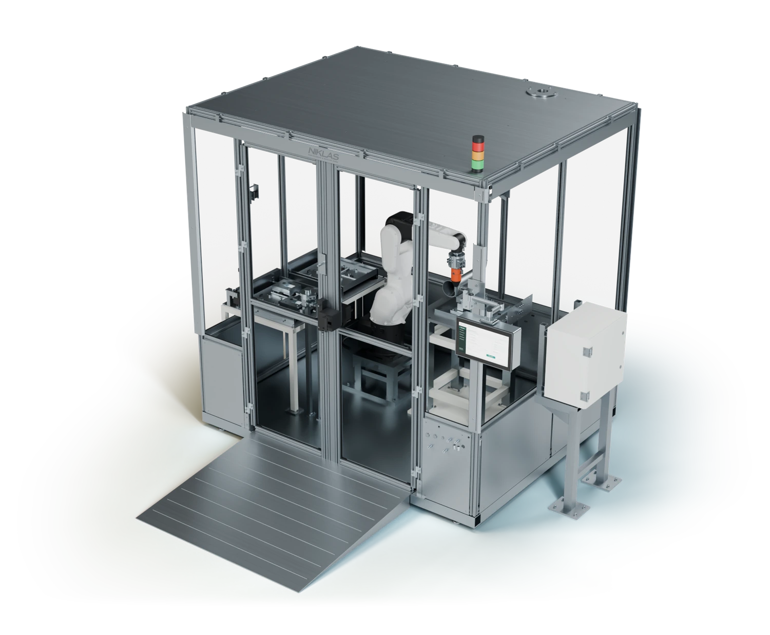
NIKLAS Surface Cell automates repetitive deburring. Tooling, workholding and parts storage are tailored to your components. Grinding or polishing is possible with suitable process equipment.
Processes
Robotics
Tooling
Magazine
Cell layout
Workholding
AUTOMATED PART FINISHING
Automate deburring. reduce manual work.
The automated deburring system combines a ROKAE industrial robot, finishing tool, workholding and parts storage. Your team supplies the blanks; the robotic deburring cell follows the defined processing sequence. Tooling, material, access and required edge quality determine the process design.
01
Supportyour team
Repetitive deburring and surface finishing can be transferred to the robot cell. This reduces monotonous manual tasks and frees up capacity for other production work.
02
Definethe process
Tooling, workpiece position and machining sequence are specified together. This establishes a clear basis for the required edge or surface finish rather than relying on judgement alone.
03
Plan forpart variants
Workholding and tooling are matched to your range of parts. Recurring variants are considered during design so the cell fits your production orders.
04
Organisematerial flow
Separate positions for raw and finished parts keep the sequence clear. Parts storage and handling are planned alongside the finishing process, not added as an afterthought.
PROCESS AND EQUIPMENT
A deburring cell with application-specific equipment.
For automated deburring, we specify the tooling, robot path and workholding around your components. With suitable tooling and process equipment, Surface Cell can also be configured as a robotic grinding or polishing cell. Material, geometry and the required edge or surface finish guide the design.
01
DEBURRING
Remove burrs from machined edges. The tool, access and robot path are specified for the contours to be processed.
02
GRINDING
Suitable tooling enables defined surfaces and contours to be ground. Abrasives and processing sequence are selected for the material and surface requirement.
03
POLISHING
The cell can be configured with the appropriate tools and consumables for polishing. The required finish is agreed using your specification and sample parts.
04
WORKHOLDING
Part-specific workholding positions the component for processing. Locators and clamps are designed around its geometry and the process forces.
05
TOOLING
The spindle, finishing tool and optional tool change form the basis of the process. Components are selected for your application.
06
Raw and finished parts
A parts magazine and defined storage positions structure material flow. Capacity, spacing and gripper are tailored to your workpieces.
07
Part variants
Recurring parts and batch sizes inform the design. Fixtures, programs and tooling are prepared for the agreed range of components.
08
CELL LAYOUT
Enclosure, fencing, access and service areas are matched to the process, available space and required protective measures.
SURFACE CELL AS A COMPLETE SYSTEM
Coordinating parts storage, robotics and processing.
The illustrated layout shows how parts storage, robotics, processing and operation work together. Select an area to explore the individual Surface Cell modules. Compare the enclosed and fenced layouts.
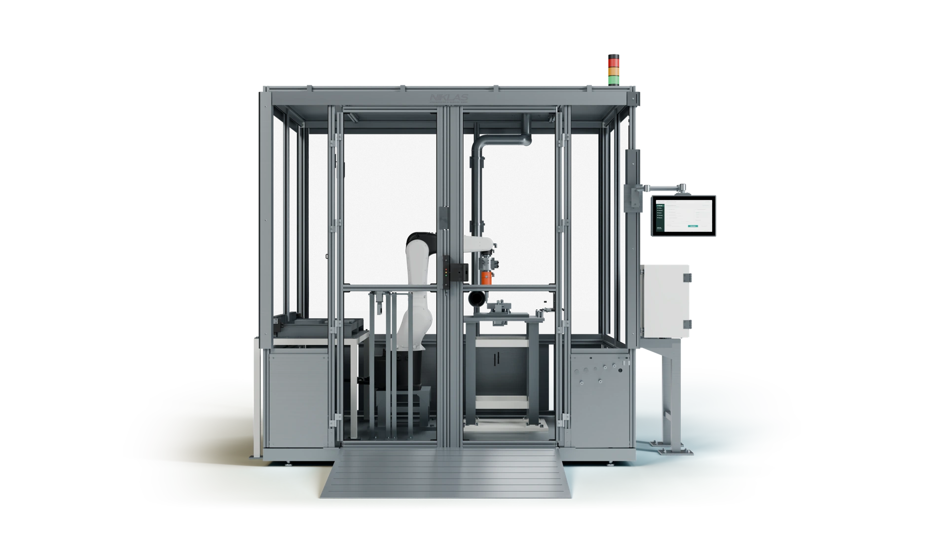
01 · PARTS MAGAZINE
Keep raw and finished parts organised.
Separate drawers and part-specific nests structure the parts supply. The magazine layout is designed for component geometry and batch size. Loading takes place in the authorised cell state.
02 · ROKAE ROBOT
Guide the tool to the processing area.
The industrial robot guides the finishing tool along the fixed workpiece. Working envelope, tool orientation and path are designed around your processing task.
03 · TOOL CHANGE
Connect part handling and finishing.
A configured tool-changing interface enables the robot to switch between the gripper and finishing tool. Matching docks hold the tools in defined positions.
04 · WORKHOLDING
Position the component for processing.
Supports, locators and clamps are tailored to your workpiece. The fixture holds the component in the intended position and leaves the processing areas accessible to the tool.
05 · OPERATOR PANEL
Keep the job and cell status in view.
The central operator panel brings together the information needed for the sequence. Program selection, status displays and operating permissions are configured for the agreed cell scope.
06 · ENCLOSURE & ACCESS
Coordinate the working area and access.
Surface Cell can be planned with an enclosure or safety fence. Access, chip or dust containment and any necessary extraction are designed for the specific finishing process.
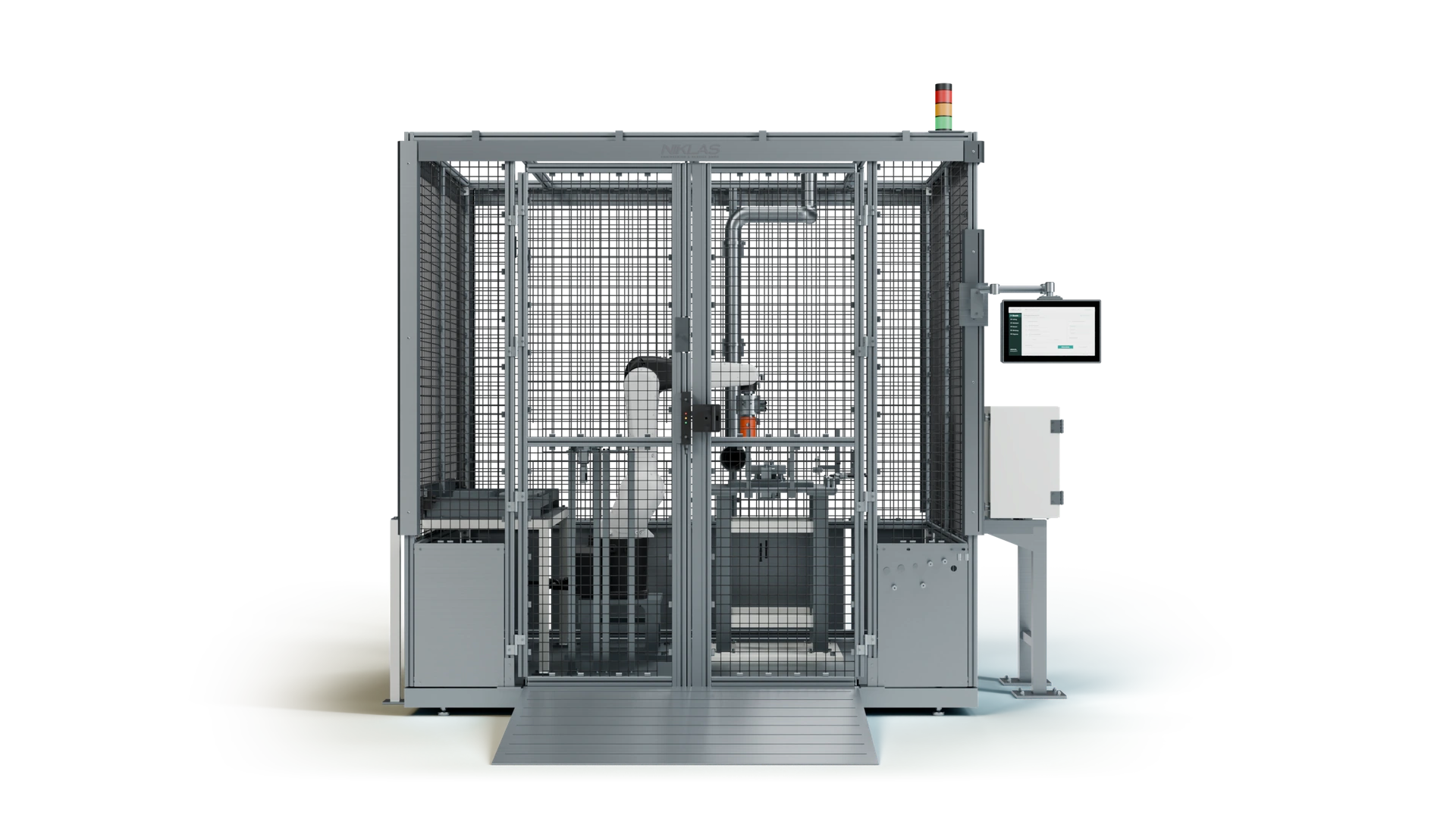
01 · PARTS MAGAZINE
Keep raw and finished parts organised.
Separate drawers and part-specific nests structure the parts supply. The magazine layout is designed for component geometry and batch size. Loading takes place in the authorised cell state.
02 · ROKAE ROBOT
Guide the tool to the processing area.
The industrial robot guides the finishing tool along the fixed workpiece. Working envelope, tool orientation and path are designed around your processing task.
03 · TOOL CHANGE
Connect part handling and finishing.
A configured tool-changing interface enables the robot to switch between the gripper and finishing tool. Matching docks hold the tools in defined positions.
04 · WORKHOLDING
Position the component for processing.
Supports, locators and clamps are tailored to your workpiece. The fixture holds the component in the intended position and leaves the processing areas accessible to the tool.
05 · OPERATOR PANEL
Keep the job and cell status in view.
The central operator panel brings together the information needed for the sequence. Program selection, status displays and operating permissions are configured for the agreed cell scope.
06 · FENCING & ACCESS
Coordinate the working area and access.
Surface Cell can be planned with an enclosure or safety fence. Access, chip or dust containment and any necessary extraction are designed for the specific finishing process.
NIKLAS CELL OPERATION
A clear view of the finishing sequence.
A clear operator interface helps your team prepare the job and identify the cell state. Displays and controls are tailored to your Surface Cell sequence.
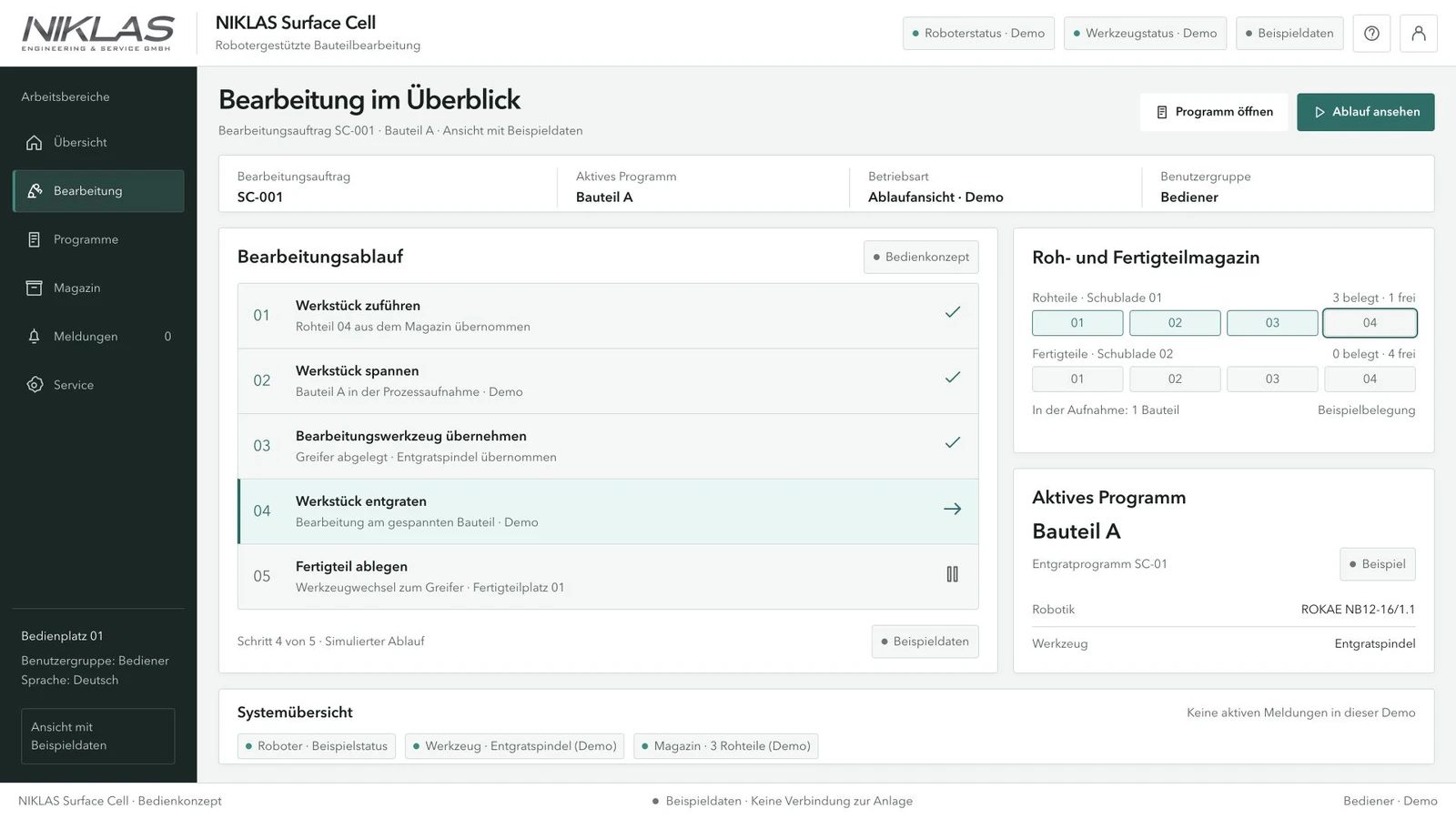
Example Surface Cell operator interface. The functional scope is agreed for your installation.
OPERATION MATCHED TO THE FINISHING PROCESS
The information needed in daily operation.
Operation, parts supply and processing need to work together. During design, we therefore consider the information the operator needs and the interventions planned for daily production.
PROGRAM AND JOB
Clearly assign the part variant to its processing sequence.
CELL STATUS
Display operating state and messages at the central operator panel.
GUIDED OPERATION
Match operating permissions and required steps to the agreed sequence.
We agree program selection, magazine occupancy and the required operating permissions with your team.
SURFACE CELL ENQUIRY
Which parts would you like to process automatically?
Send us component photos or drawings, material, burr locations, required edge quality, batch size and your current finishing process. For grinding or polishing, include the required surface finish. This helps us define the appropriate deburring cell and process equipment.